Graphene growth on a carbon-containing semiconductor layer

a technology of graphene and silicon carbide, which is applied in the direction of instruments, record information storage, transportation and packaging, etc., can solve the problems of prior attempts to grow a single crystalline silicon carbide layer on a single crystalline silicon substrate, polycrystalline silicon carbide growth on silicon, and inability to provide a 200 mm or 300 mm substrate containing a graphene layer

Active Publication Date: 2011-02-24
GLOBALFOUNDRIES US INC
View PDF3 Cites 40 Cited by
  • Summary
  • Abstract
  • Description
  • Claims
  • Application Information

AI Technical Summary

Problems solved by technology

Such unavailability of silicon carbide (SiC) substrates currently makes it impossible to provide a 200 mm substrate or a 300 mm substrate containing a graphene layer.
Prior attempts to grow a single crystalline silicon carbide layer on a single crystalline silicon substrate have been unsuccessful because of the large lattice mismatch between a silicon crystal and a silicon carbide crystal.
That is, the high stress that exists due to lattice mismatch between the silicon and silicon carbide lattices produces polycrystalline non-commensurate growth of silicon carbide on silicon.

Method used


Image

  • Graphene growth on a carbon-containing semiconductor layer
  • Graphene growth on a carbon-containing semiconductor layer
  • Graphene growth on a carbon-containing semiconductor layer

Examples


first embodiment

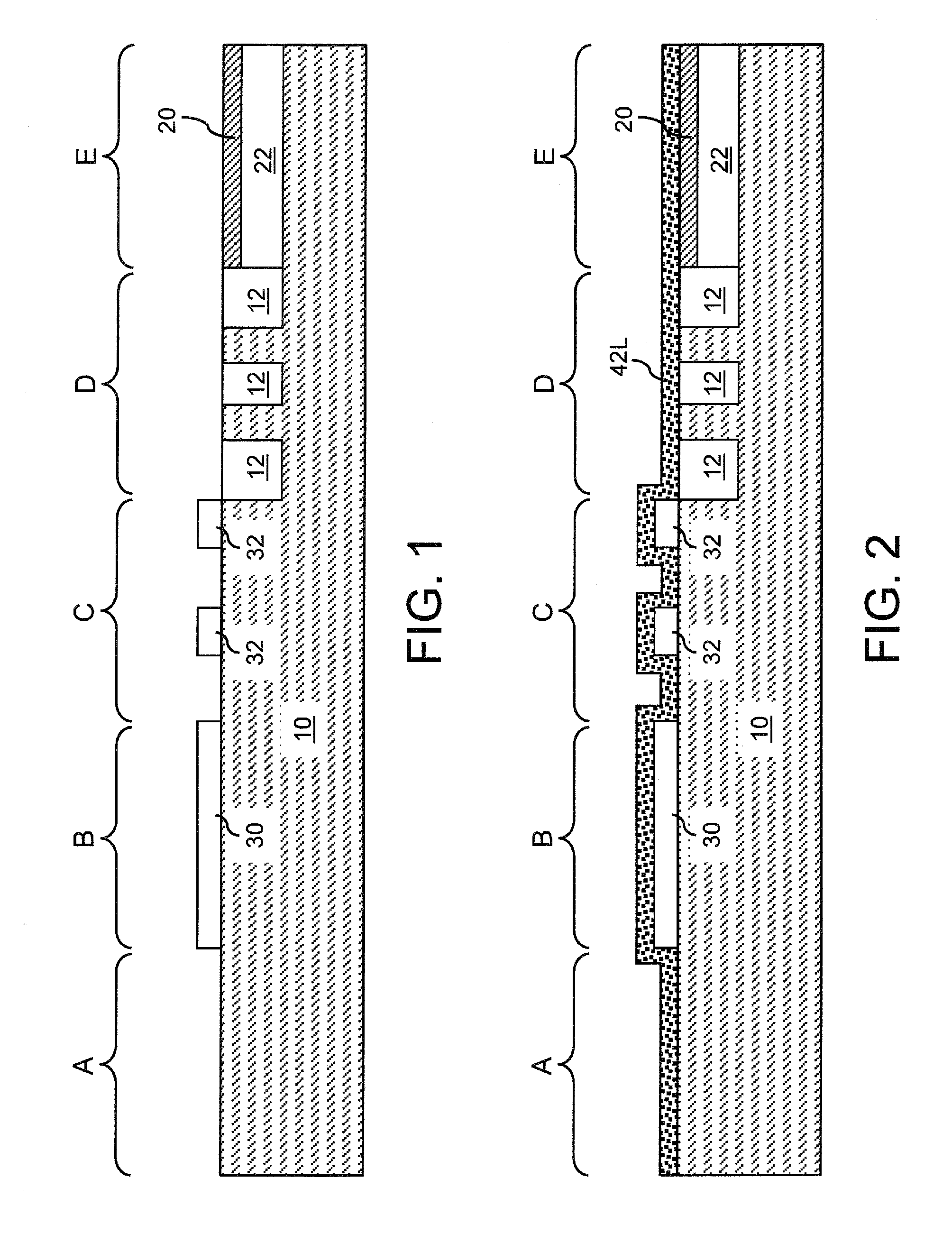
[0019]Referring to FIG. 1, a semiconductor structure according to the present invention is shown. The semiconductor substrate 10 includes a semiconductor material including silicon. The semiconductor substrate 10 may be a commercially available semiconductor substrate having a diameter from 150 mm to 300 mm, and preferably from 200 mm to 300 mm, and having a thickness from 500 micron to 1.0 mm. Preferably, the semiconductor substrate 10 is a single crystalline silicon-containing-semiconductor substrate, i.e., a single crystalline substrate containing silicon or a silicon alloy. The singe crystalline silicon-containing semiconductor substrate may include a single crystalline silicon material, a single crystalline silicon-germanium alloy material, a single crystalline silicon-carbon alloy material, or a single crystalline silicon-germanium-carbon alloy material. If the semiconductor substrate 10 is a single crystalline silicon-containing-semiconductor substrate, the semiconductor subs...

second embodiment

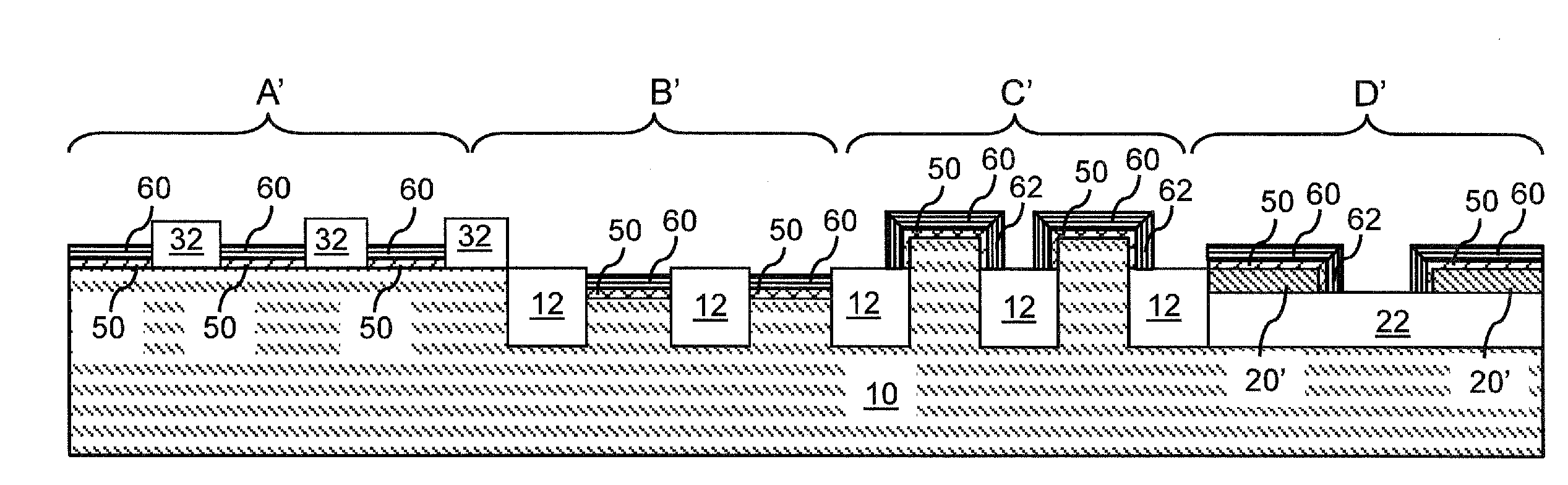
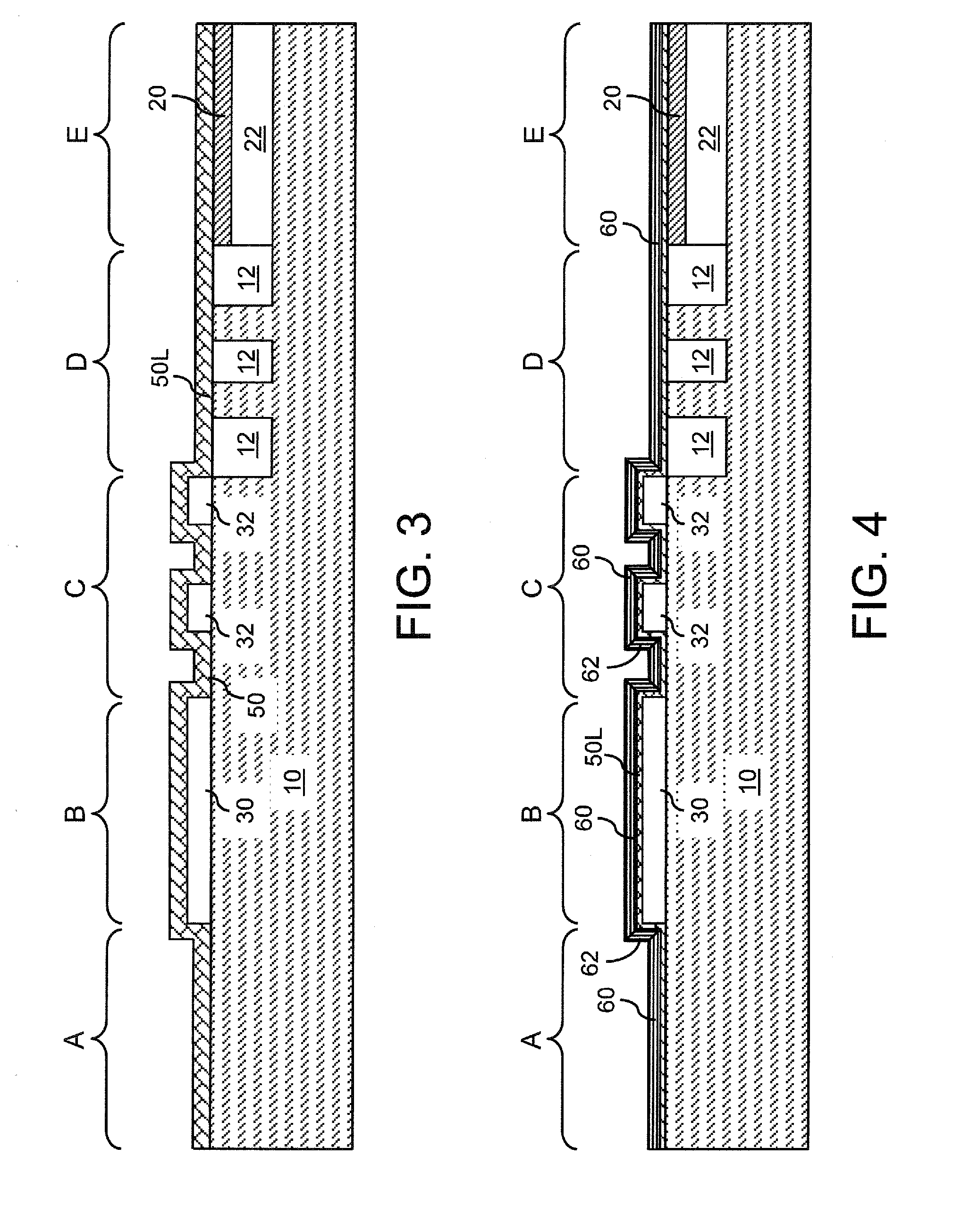
[0020]For the purpose of description of the present invention, the semiconductor substrate 10 includes a first region A having a planar exposed top surface of the semiconductor substrate 10, a second region B having an overlying dielectric material portion 30 that is located over the top surface of the semiconductor substrate 10, a third region C having patterned overlying dielectric material portions 32 that are located over the top surface of the semiconductor substrate 10, a fourth region D having exposed semiconductor surfaces of the semiconductor substrate 10 located between embedded dielectric material portions 12, and a fifth region D having a buried insulator layer 22 and a top semiconductor layer 20 having a single crystalline silicon-containing-semiconductor material. The overlying dielectric material portion 30 may be a silicon oxide layer, a silicon nitride layer, or a combination thereof. The patterned overlying dielectric material portions 32 may be portions of a silic...


PUM

PropertyMeasurementUnit
thicknessaaaaaaaaaa
temperatureaaaaaaaaaa

Abstract

A semiconductor-carbon alloy layer is formed on the surface of a semiconductor substrate, which may be a commercially available semiconductor substrate such as a silicon substrate. The semiconductor-carbon alloy layer is converted into at least one graphene layer during a high temperature anneal, during which the semiconductor material on the surface of the semiconductor-carbon alloy layer is evaporated selective to the carbon atoms. As the semiconductor atoms are selectively removed and the carbon concentration on the surface of the semiconductor-carbon alloy layer increases, the remaining carbon atoms in the top layers of the semiconductor-carbon alloy layer coalesce to form a graphene layer having at least one graphene monolayer. Thus, a graphene layer may be provided on a commercially available semiconductor substrate having a diameter of 200 mm or 300 mm.

Description

BACKGROUND[0001]The present invention relates to a method of forming a graphene layer on a carbon-containing semiconductor layer, and a structure obtained by the same.[0002]Graphene is a monolayer of a two-dimensional sheet of carbon atoms. A graphene layer has a thickness of about 0.34 nm, i.e., which is approximately the atomic diameter of a single carbon atom. Graphene provides excellent in-plane conductivity. Semiconductor devices employing graphene have been suggested in the art to provide high-density and high-switching-speed semiconductor circuits.[0003]To enable mass manufacturing of such semiconductor devices, it is desirable to grow graphene on commercially available 200 mm or 300 mm semiconductor substrates for compatibility with manufacturing at modern microelectronic fabrication facilities. While it is known that a graphene layer may be grown by direct epitaxial deposition of carbon atoms on, i.e., addition of carbon atoms onto the surface of, a single crystalline silic...

Claims


Application Information

Patent Timeline
Patent Type & Authority Applications(United States)
IPC IPC(8): H01L29/24H01L21/311H01L21/20B32B9/00
CPCB82Y30/00B82Y40/00C01B31/0446C01B2204/04H01L21/02381Y10T428/265H01L21/0245H01L21/02527H01L21/0262H01L21/02664H01L21/02667H01L21/02447C01B32/184H01L29/045H01L29/1606H01L29/1608H01L29/161
Inventor CHU, JACK O.DIMITRAKOPOULOS, CHRISTOS D.GRILL, ALFREDSUNG, CHUN-YUNG
Owner GLOBALFOUNDRIES US INC
Why Eureka
Try Eureka