
Externally fused and resistively loaded safety capacitor

Active Publication Date: 2011-02-24
KEMET ELECTRONICS
View PDF6 Cites 58 Cited by
  • Summary
  • Abstract
  • Description
  • Claims
  • Application Information

AI Technical Summary

Benefits of technology

[0011]A particular advantage of the present invention is that the invention offers a great deal of design flexibility since different types of safe circuits can now be incorporated on the substrate and integrated with the capacitors at an affordable cost. In its simpler form, a resistor of lower resistance than the capacitor can be provided parallel to the capacitor to allow for a controlled discharge over a shorter time period.
[0012]These and other advantages, as will be realized, are provided in a safe capacitor with a resistive load failure mode. The safe capacitor has a first external termination, an internal termination and a second external termination. At least one capacitive unit comprising a first conductor and a second conductor with a first lead is connected to the first conductor and a second lead is connected to the second conductor wherein the first lead is electrically connected to the first external termination and the second lead is connected to the internal termination. At least one safe circuit is attached to the capacitor element wherein the safe circuit comprises a third lead and a fourth lead and wherein the third lead is connected to the internal termination and the fourth lead is connected to the second external termination. The safe circuit comprises a fuse and a resistor in parallel between the third lead and the fourth lead.
[0013]Yet another embodiment is provided in an electrical circuit protected against overload. The circuit comprises a circuit trace. A safe capacitor is attached to the circuit trace wherein the safe capacitor has a first external termination, an internal termination and a second external termination. At least one capacitive unit comprising a first conductor and a second conductor with a first lead connected to the first conductor and a second lead connected to the second conductor. The first lead is electrically connected to the first external termination and the second lead is connected to the internal termination. A safe circuit is attached to the capacitor element wherein the safe circuit comprises a third lead and a fourth lead and wherein the third lead is connected to the internal termination and the fourth lead is connected to the second external termination and the safe circuit comprises a fuse and a resistor in parallel between the third lead and the fourth lead. When exposed to an excessive current the fuse opens thereby converting the safe circuit to a resistive circuit.
[0014]Yet another embodiment is provided in a method for manufacturing a safe capacitor. The method includes: providing at least one capacitive unit comprising alternating conductive plates of opposing polarity separated by a dielectric wherein first plates of the alternating conductive plates are in electrical contact with a first termination and second plates of the alternating conductive plates are in electrical contact with a second termination; providing a safe circuit comprising a third terminal and a fourth terminal with a fuse and a resistor in electrical parallel between the third terminal and the fourth terminal; orienting the capacitive units to form a stack of capacitive units; attaching the safe circuit to the stack of capacitive units wherein the third terminal is in electrical contact with the second termination to form a safe capacitor precursor; attaching external terminations to the safe capacitor precursor wherein a first external termination is in electrical contact with the first termination and a second external termination is in electrical contact with the fourth terminal.
[0015]A particularly preferred embodiment is provided by having the resistor connected in parallel to the capacitor to allow for rapid discharge with a fuse in series to open in an overcurrent condition resulting in a resistive failure.

Problems solved by technology

In cases where capacitor failure is due to an internal short, or an electrical overload, the failure itself can cause damage to the remaining circuit or the failure eliminates protection of the remaining circuit from subsequent events.
If capacitor failure results in a direct short, for example, the dampening effect on the remaining circuit is lost resulting in potential un-dampened high loads.
This failure mode renders the capacitor non-functional but does protect the circuit from an overload condition.
However, certain open mode failures, caused by cracked capacitors as an example, when exposed to voltage, can result in metal migration creating an intermittent open or short over time.
It is known that voltage in the presence of humidity results in an increased rate of metal migration accelerating the failure.
It is cost prohibitive when utilized to generate circuits one part at a time.
Implementing the cited prior art is difficult for, at least, two reasons.
This requires an extensive amount of parts handling, tooling and automation.
Special tooling is required to properly locate each capacitor at each printing step, thus requiring a high level of capitalization.
The second issue is that thick film materials are designed to be fired in an air atmosphere.
PME, typically utilizing palladium and silver, are cost prohibitive in many cases.
Unfortunately, BME systems must be fired in a reducing atmosphere in order to keep the nickel from oxidizing.
Therefore, the practice of utilizing thick film technology is limited to a small mix of products that utilizes the PME electrode system and cannot be applied to BME electrode systems because of the incompatibility of the air fired material systems.

Method used


Image

  • Externally fused and resistively loaded safety capacitor
  • Externally fused and resistively loaded safety capacitor
  • Externally fused and resistively loaded safety capacitor

Examples


Embodiment Construction

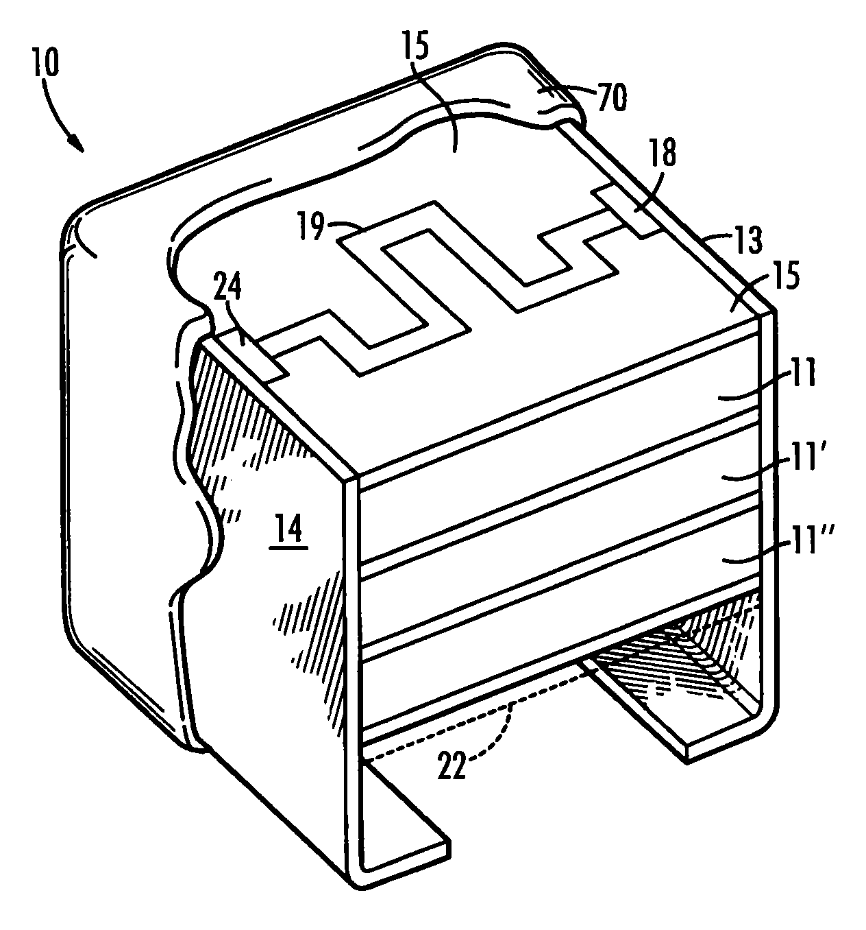
[0040]The present invention is directed to an improved capacitor with integral components, most preferably resistors and fuses, linked collectively or individually in parallel or series with the capacitor. The improved capacitor mitigates damage which occurs upon catastrophic failure of the capacitive component and provides a means for rapidly discharging a capacitor.

[0041]The invention will be described with reference to the figures forming an integral part of the present application. Throughout the various figures similar elements may be numbered accordingly.

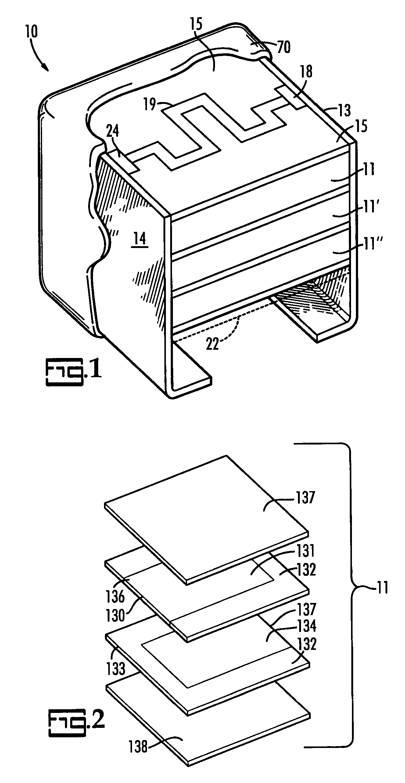
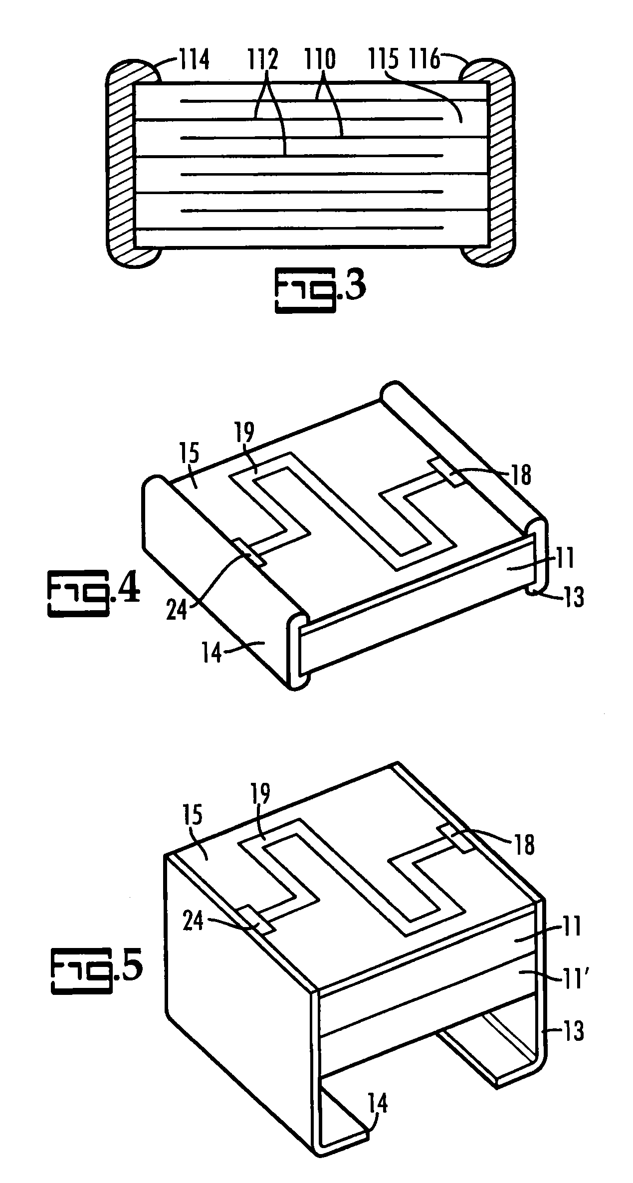
[0042]More specifically, provided herein is a monolithic stacked multilayer ceramic capacitor (MLCC) within a lead frame that incorporates a ceramic substrate containing a resistor, fuse or combination thereof that is connected in parallel, or series, to one or more capacitors in a discrete unit. The use of a ceramic substrate offers a relatively cost effective way of combining these functionalities without having to match the...


PUM

PropertyMeasurementUnit
Flexibilityaaaaaaaaaa
Electrical conductoraaaaaaaaaa

Abstract

A capacitor with a combined with a resistor and / or fuse is described. This safe capacitor can rapidly discharge through the resistor when shorted. The presence of a fuse in series with the capacitor and results in a resistive failure when this opens during and overcurrent condition. Furthermore, the presence of a resistor in parallel to the capacitor allows the energy to be rapidly dissipated when a failure occurs.

Description

BACKGROUND OF INVENTION[0001]The present invention is related to a capacitor with integral components, preferably, resistors and fuses, wherein failure of the capacitor results in a resistively loaded or protected circuit.[0002]Capacitors are utilized in virtually every electronic circuit and their function is well documented. As with any electronic component capacitors are not immune to failure. Failures can be caused by physical strain, by electrical overloads, or by a myriad of other causes. In cases where capacitor failure is due to an internal short, or an electrical overload, the failure itself can cause damage to the remaining circuit or the failure eliminates protection of the remaining circuit from subsequent events. If capacitor failure results in a direct short, for example, the dampening effect on the remaining circuit is lost resulting in potential un-dampened high loads. Designs have been developed that allow the capacitor to fail in an open mode, thus minimizing the o...

Claims


Application Information

Patent Timeline
IPC IPC(8): H01G4/06H01G4/00H01G4/38H01G7/00
CPCH01G2/16H01G4/30H01G4/40Y10T29/435Y10T29/43Y10T29/417Y10T29/49002
Inventor BULTITUDE, JOHNMCCONNELL, JOHN E.
Owner KEMET ELECTRONICS
Features
  • Generate Ideas
  • Intellectual Property
  • Life Sciences
  • Materials
  • Tech Scout
  • Unparalleled Data Quality
  • Higher Quality Content
  • 60% Fewer Hallucinations
Learn More