
Method for separating and removing dicing surface protection tape from object to be cut

Inactive Publication Date: 2011-03-03
NITTO DENKO CORP
View PDF4 Cites 18 Cited by
  • Summary
  • Abstract
  • Description
  • Claims
  • Application Information

AI Technical Summary

Benefits of technology

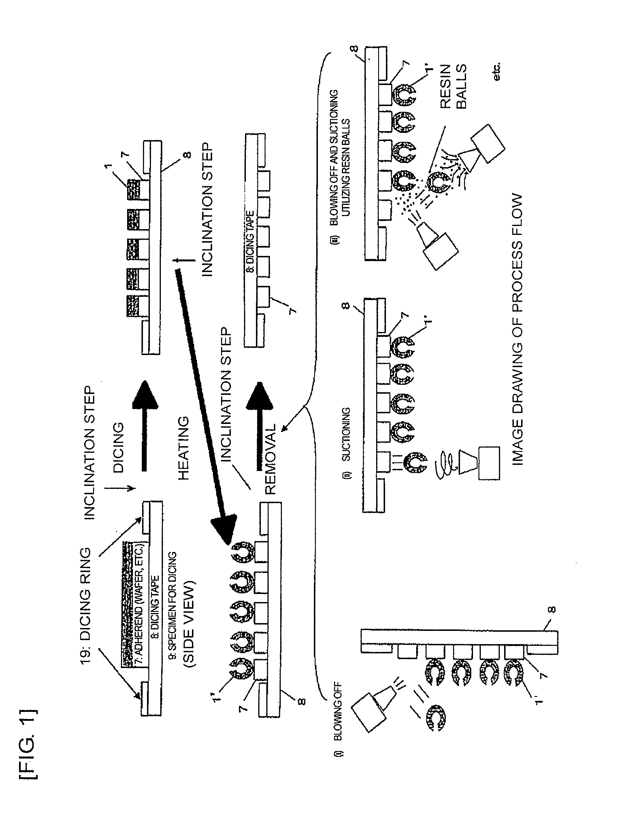
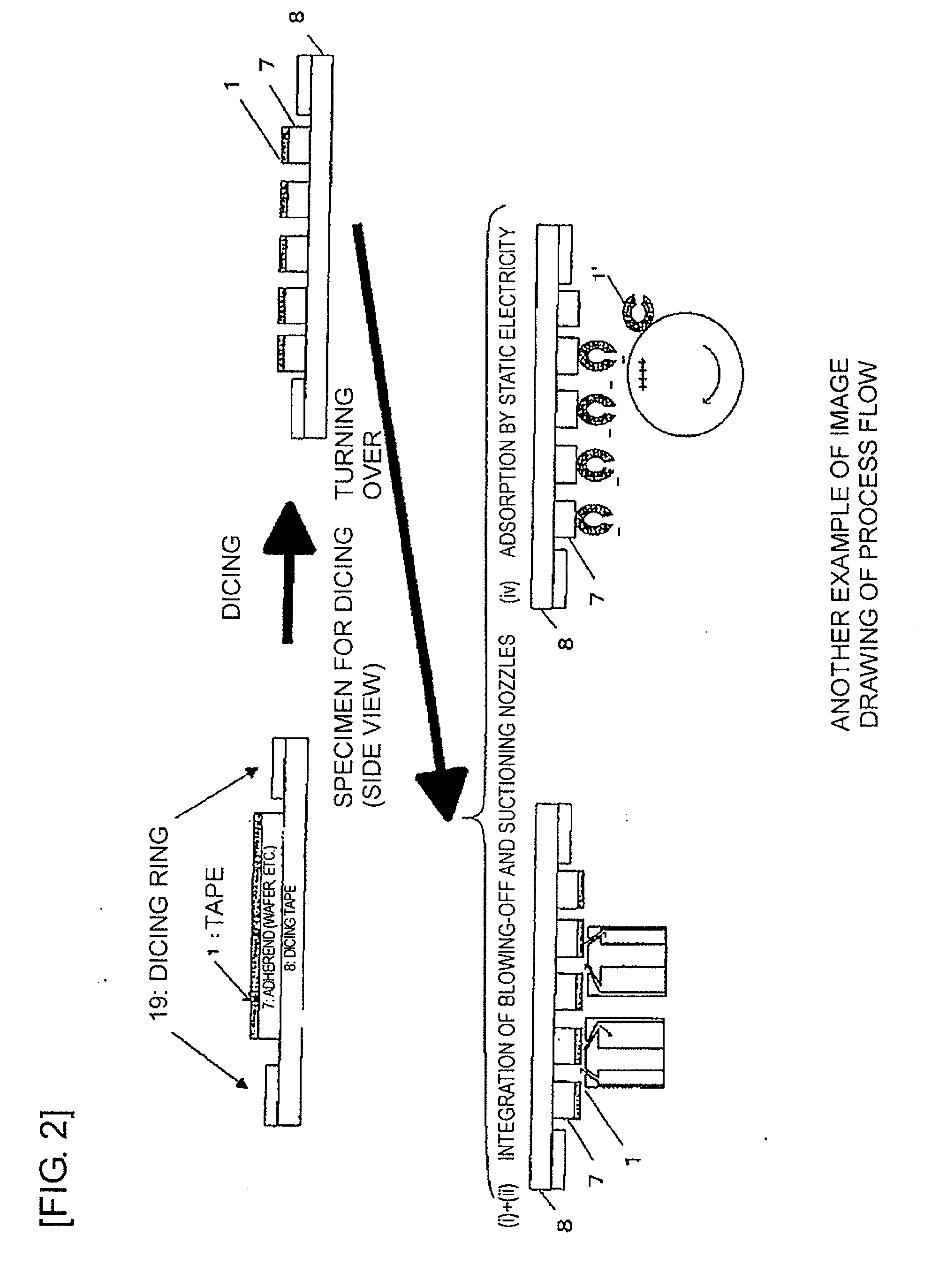
[0047]If the composite body is inclined as described above, cut-off portions of the dicing surface protection tape, even though allowed to roll over the object to be cut, will roll over according to the inclination. Thus, it is possible to prevent the cut-off portions from adhering to surfaces of a dicing tape. In addition, if the composite body is inclined to 90° or greater, the cut-off portions of the dicing surface protection tape no longer roll over a surface of the object to be cut, though the cut-off portions may simply drop. Thus, the cut-off portions do not adhere to surfaces of a dicing tape, a dicing ring and the like. For such reasons, the present invention can exert the above-described advantageous effects by separating and removing the dicing surface protection tape cut with the object to be cut inclined.
[0048]As means for separating and removing the dicing surface protection tape in the present invention, it is possible to adopt means which uses an apparatus capable of suctioning or blowing off the tape by a difference in atmospheric pressure, means which concomitantly uses resin particles along with the blowing-off means to take advantage of the kinetic energy of the resin particles as energy for separating and removing the tape, means which utilizes static electricity to adsorb the tape, or the like. At that time, it is possible to concomitantly use the application of ultrasonic transducer-induced vibrations from the rear surface of the object to be cut. If the means for blowing off the tape by a difference in atmospheric pressure is adopted, it is possible to separate and remove the surface protection tape by blowing it off, while applying a stimulus to the tape by using a heated gas.
[0049]Specific examples of the means which uses an apparatus capable of suctioning and / or blowing off the tape by a difference in atmospheric pressure include blowing a gas by using various types of air cleaners, blowers, and the like, suctioning the tape by a nozzle connected to a vacuum apparatus or the like, and blowing a gas at the tape or suctioning the tape by the concomitant use of these apparatus.
[0050]The blow-off and suction strengths of these means may be set optionally to the extent of enabling separation and removal according to the present invention. However, the strengths have to be at such levels as not to destroy the object to be cut or change the physical properties thereof. When blowing a gas at the tape, there is the need to consider, for example, a direction in which the gas is blown, in order to prevent cut-off portions of the dicing surface protection tape and powdery particulates from flying off, adhering to a dicing tape and a dicing ring, and consequently causing problems in a subsequent pick-up process or contaminating chips.
[0051]Accordingly, it is desirable to not only simply blow a gas by using an air cleaner or a blower, but also place a suction nozzle for suctioning the gas, in some cases, in a position where the blown-off gas is collected together with the separated-off portions of the surface protection tape.
[0052]In addition, the gas has to be forcibly blown into between the object to be cut and the dicing surface protection tape, so that, as the result of the gas being blown at the ends of the cut-off portions of the dicing surface protection tape bonded to the object to be cut, the tape ends separate from the object to be cut. Therefore, the angle at which the gas is blown with respect to a surface of the object to be cut needs to be sufficiently small. Otherwise, the blown gas behaves so as to hold down the dicing surface protection tape on the object to be cut, and therefore, the tape may not be fully separated off.

Problems solved by technology

Such contamination may cause the electronic component to become defective.
However, the conventional protection tape is difficult to separate and remove separately from the individual pieces of the wafer, and therefore, has not yet been put into practical use.
Such a thin-film wafer is extremely fragile and liable to crack, however.
For this reason, it has become increasingly difficult to separate and remove a protection tape from the wafer divided into individual pieces.
In this method, the protection tape is difficult to separate and remove in the absence of any trigger for the separation of the protection tape.
However, the transformation of the protection tape resulting from the abovementioned contraction, particularly heat shrinkage, causes not only warpage but also random shape distortions, such as rumples, in the protection tape.
If separation and collection are performed under such conditions as described above, particularly in the case of blowing air, individual separated-off portions of the dicing surface protection tape are likely to be blown away, or glide, roll or bounce over surfaces of an object to be cut at that time.
Consequently, the surfaces of the object to be cut may be contaminated or damaged.
Such adhered portions of the tape are difficult to separate off.
Thus, it is no longer possible to stretch the dicing tape as a whole as intended.
Accordingly, in an apparatus for automatically picking up the articles, a pick-up jig fails to precisely have contact with the articles at preset positions and cannot unfailingly pick up the articles.
As a result, defective articles arise for the reason that, for example, a positional relationship between the pick-up jig and the object to be cut goes out of order.
In addition, a method for separating and removing a dicing surface treatment tape by using a separating tape has the potential problem that there arise unseparated portions of the tape or the separating tape comes into contact with the object to be cut, unless the height of the dicing surface treatment tape is uniform.
Another problem is that separation using tweezers is manual work and is, therefore, not efficient.

Method used


Image

  • Method for separating and removing dicing surface protection tape from object to be cut
  • Method for separating and removing dicing surface protection tape from object to be cut
  • Method for separating and removing dicing surface protection tape from object to be cut

Examples


working examples

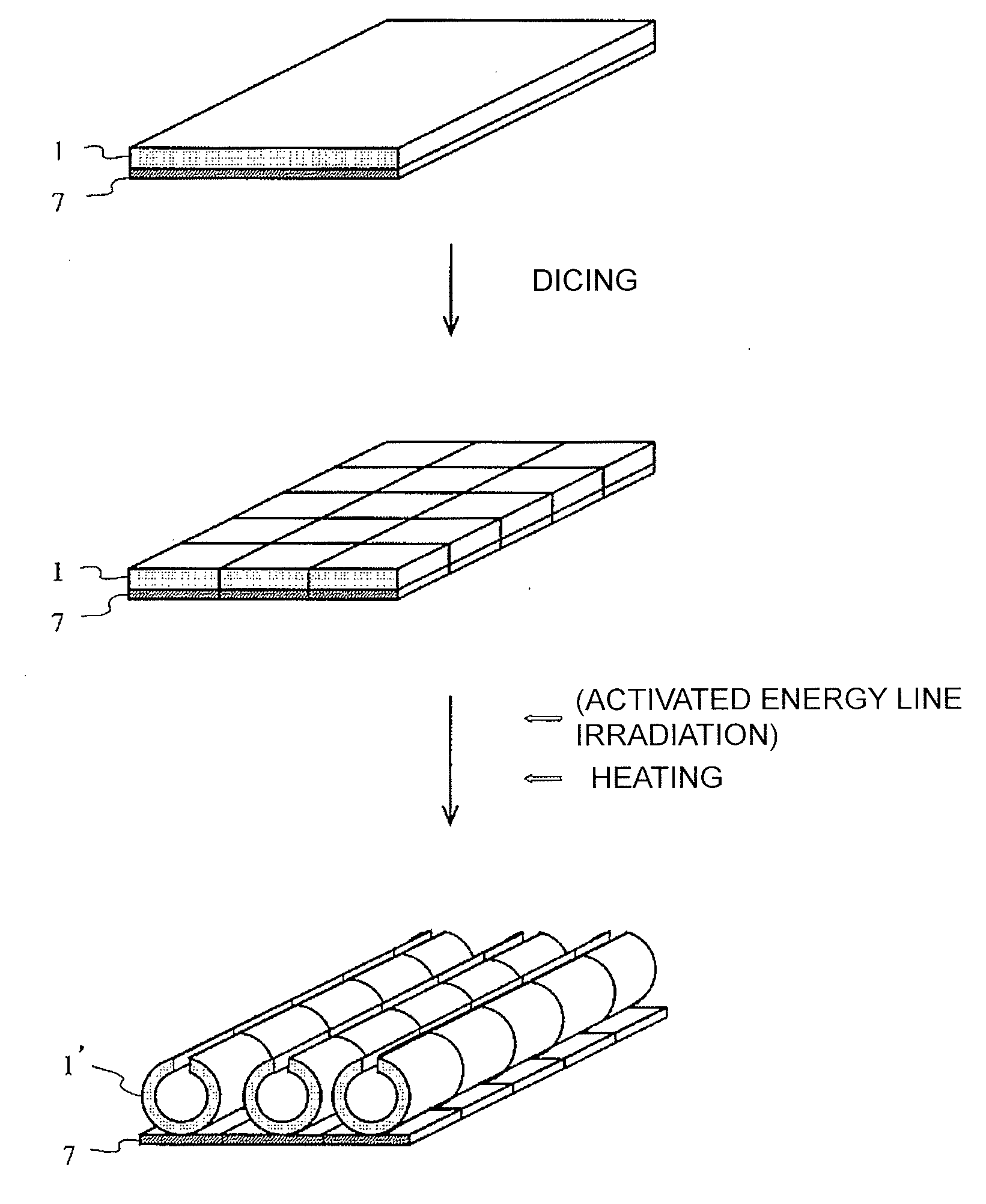
[0250]Hereinafter, a surface protection tape used in a method of the present invention will be described in detail, according to working examples. However, the present invention is not limited to these working examples in which the surface protection tape is used. Note that the shear elastic moduli of an elastic layer and a rigid film layer and the tack strength of the elastic layer with respect to a shrinkable film were measured as described below. In addition, r / L, which is an index for determining whether the surface protection tape functions as a cylindrical roll or rolls, was defined by a method described below.

[Measurement of Rigid Film Layer's Young's Modulus (80° C.)]

[0251]The Young's modulus of the rigid film layer was measured in compliance with JIS K7127 by using the below-described method. As a tensile tester, Autograph AG-1kNG (with a warming hood) made by Shimadzu was used. A rigid film cut out to a 200 mm-long×10 mm-wide size was attached with an inter-chuck distance ...

manufacturing example 1

Manufacture of Activated Energy Line-Hardening Tackiness Agent Layer (1)

[0259]50% of a hydroxyl group derived from 2-hydroxyethyl acrylate of an acrylic-based polymer [obtained by copolymerizing a material having a composition of 2-ethylhexyl acrylate:morpholyl acrylate:2-hydroxyethyl acrylate=75:25:22 (molar ratio)] was combined with methacryloyl oxyethyl isocyanate (2-isocyanatoethyl methacrylate) to manufacture an acrylic-based polymer having a methacrylate group in the side chain thereof.

[0260]15 pts. wt. of Aronix M320 (trimethylolpropane PO-modified (n≈2) triacrylate made by Toagosei), which is a photopolymerizable cross-linking agent, 1 pts. wt. of a photoinitiator (“IRGACURE” 651″ (trade name) made by Ciba-Geigy), and 1 pts. wt. of an isocyanate-based cross-linking agent (“CORONATE L” (trade name)) were blended with 100 pts. wt. of this acrylic-based polymer having a methacrylate group in the side chain thereof, to prepare an activated energy line-hardening tackiness agent.

[...

manufacturing example 2

Manufacture of Non-activated Energy Line-Hardening Tackiness Agent Layer (1)

[0262]0.7 pts. wt. of an epoxy-based cross-linking agent (made by Mitsubishi Gas Chemical Company under the trade name “TETRAD-C”), and 2 pts. wt. of an isocyanate-based cross-linking agent (“CORONATE L” (trade name)) were blended with a 100 pts. wt. of an acrylic-based copolymer [obtained by copolymerizing a material having the composition of butyl acrylate:acrylic acid=100:3 (weight %)] to prepare a non-activated energy line-hardening tackiness agent.

[0263]The non-activated energy line-hardening tackiness agent thus obtained was coated on a separating sheet (made by Mitsubishi Polyester Film under the trade name “MRF38”) by using an applicator. After that, the volatile constituents of the tackiness agent, such as a solvent, were dried off, thereby obtaining a laminated body in which a 30 μm-thick non-activated energy line-hardening tackiness agent layer was provided on the separating sheet.


PUM

PropertyMeasurementUnit
Pressureaaaaaaaaaa
Adhesion strengthaaaaaaaaaa
Electrostatic forceaaaaaaaaaa

Abstract

The present invention is intended to provide a method for protecting a surface of an object to be cut from contamination due to the adhesion of dust and the like, including cutting scraps, by bonding a surface protection tape to the surface of the object to be cut, and cutting the surface protection tape together with the object to be cut in a dicing process and, after the dicing process, easily separating and removing the protection tape from individual chips. To this end, there is provided a method in which a dicing surface protection tape is bonded to a surface of an object to be cut, the tape is cut together with the object to be cut, and then the dicing surface protection tape is removed with the object to be cut inclined.

Description

BACKGROUND OF THE INVENTION[0001]1. Field of the Invention[0002]The present invention relates to a separation and removal method applied after an object to be cut is diced with a dicing surface protection tape bonded thereto in a process of dividing the object to be cut, including semiconductor wafers, into individual pieces (dicing).[0003]2. Description of the Related Art[0004]Conventionally, a circuit-formed surface of a wafer remains exposed in a process of dividing a wafer into individual pieces (hereinafter referred to as a dicing process) performed after a back-grinding process. Accordingly, it has been premised that cutting water and dust, such as cutting scraps, arising from wafer cutting during dicing adhere to the circuit-formed surface, thus contaminating the exposed circuit-formed surface of surfaces of an electronic component. Such contamination may cause the electronic component to become defective. In this case, a study is made to protect the electronic component from...

Claims


Application Information

Patent Timeline
IPC IPC(8): B32B38/10
CPCB32B38/10Y10T156/1939B32B2310/028B32B2310/04B32B2310/0825H01L21/67132H01L21/6836H01L2221/68318H01L2221/68327H01L2221/68386Y10T156/1917Y10T156/1911Y10T156/1142Y10T156/1137Y10T156/1121Y10T156/1153Y10T156/1158Y10T156/1922B32B2038/1891
Inventor SUGIMURA, TOSHIMASANISHIO, AKINORIKIUCHI, KAZUYUKI
Owner NITTO DENKO CORP
Learn More