Exposure method, exposure apparatus, and device manufacturing method

a technology of exposure apparatus and manufacturing method, which is applied in the direction of photomechanical apparatus, instruments, printing, etc., can solve the problems of inability to accurately align the scale, inability to accurately measure the angle of the grating pitch, etc., to achieve good precision and precise alignment

Active Publication Date: 2011-03-03
NIKON CORP
View PDF7 Cites 11 Cited by
  • Summary
  • Abstract
  • Description
  • Claims
  • Application Information

AI Technical Summary

Benefits of technology

[0015]According to the apparatus, the control system drives the movable body using measurement results of the first measurement system at least during scanning exposure, and in at least a part of a period besides during the scanning exposure, uses measurement results of the second measurement system, during a series of operations to sequentially form the pattern on the plurality of shot areas on the object.

Problems solved by technology

However, requirements for a stage position control with higher precision are increasing due to finer patterns that accompany higher integration of semiconductor devices, and now, measurement errors resulting from air fluctuation generated by temperature variation of the atmosphere on the beam path of the laser interferometer or by temperature gradient has come to occupy a large percentage in the overlay budget.
However, while the encoder is superior in the viewpoint of measurement reproducibility because of using a scale, it is inferior for the mechanical instability (drift of the grating pitch, fixed location drift, thermal expansion a

Method used


Image

  • Exposure method, exposure apparatus, and device manufacturing method
  • Exposure method, exposure apparatus, and device manufacturing method
  • Exposure method, exposure apparatus, and device manufacturing method

Examples


Embodiment Construction

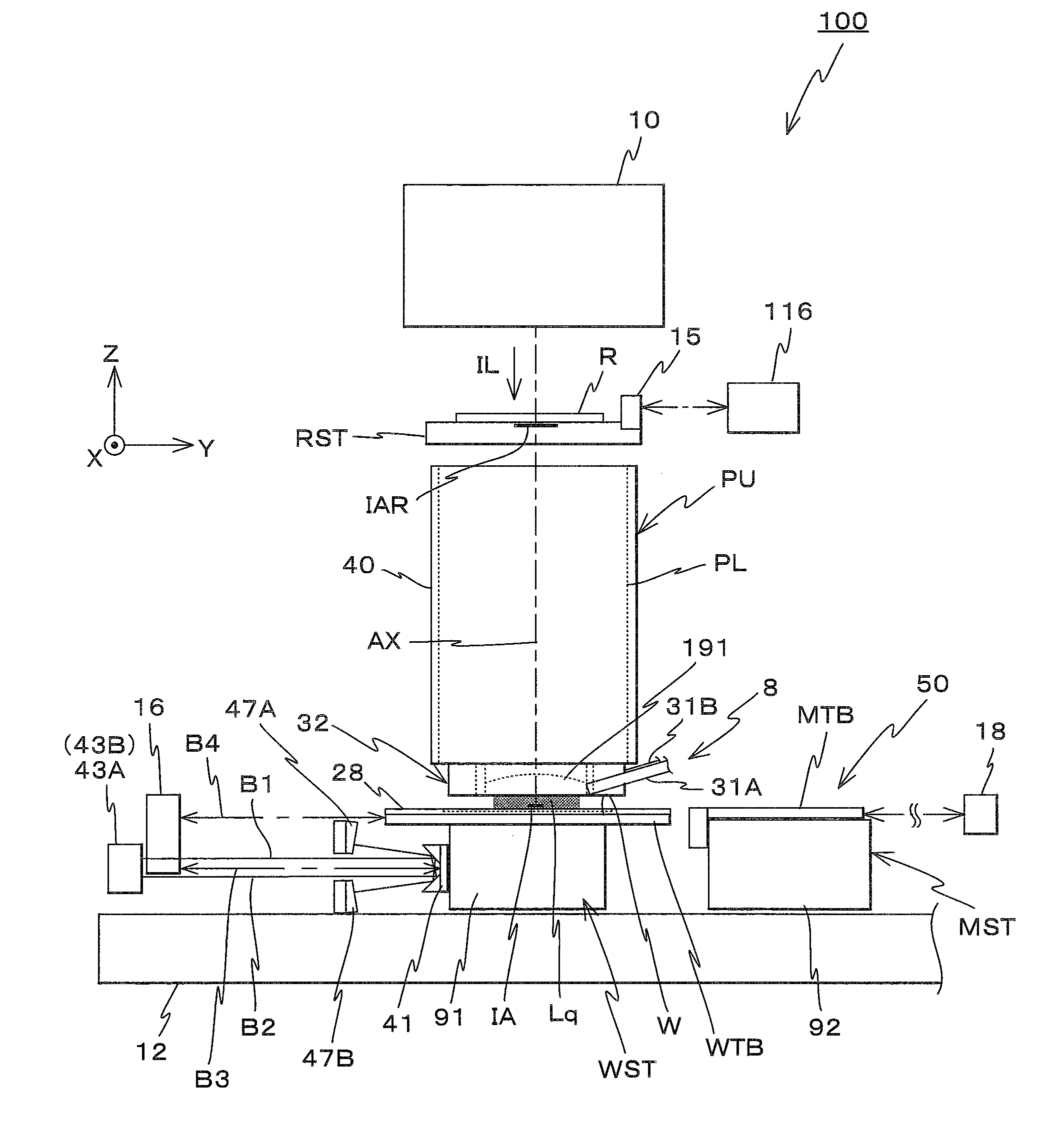
[0034]An embodiment of the present invention will be described below, with reference to FIGS. 1 to 14. FIG. 1 shows a schematic configuration of an exposure apparatus 100 in the embodiment.

[0035]Exposure apparatus 100 is a projection exposure apparatus by the step-and-scan method, or a so-called scanner. As it will be described later, a projection optical system PL is arranged in the embodiment, and in the description below, a direction parallel to an optical axis AX of projection optical system PL will be described as the Z-axis direction, a direction within a plane orthogonal to the Z-axis direction in which a reticle and a wafer are relatively scanned will be described as the Y-axis direction, a direction orthogonal to the Z-axis and the Y-axis will be described as the X-axis direction, and rotational (inclination) directions around the X-axis, the Y-axis, and the Z-axis will be described as θx, θy, and θz directions, respectively.

[0036]As shown in FIG. 1, exposure apparatus 100 ...


PUM

PropertyMeasurementUnit
Lengthaaaaaaaaaa
Timeaaaaaaaaaa
Speedaaaaaaaaaa

Abstract

Positional information of a stage is obtained using an interferometer system only during an exposure time when a constant speed drive of the stage is performed to form a pattern. Therefore, the linear measurement of the positional information is secured enough, which makes it possible to linearly drive the stage with high accuracy. Meanwhile, between an acceleration time and a deceleration time in which a step drive is performed, the positional information of the stage is obtained using an encoder system and a surface position measurement system. Therefore, measurement reproducibility of the positional information is sufficiently secured by the mechanical stability of a diffraction grating, which makes it possible to drive the stage precisely to the starting position of the constant speed drive.

Description

CROSS-REFERENCE TO ABLATED APPLICATIONS[0001]This non-provisional application claims the benefit of Provisional Application No. 61 / 236,668 filed Aug. 25, 2009, the disclosure of which is hereby incorporated herein by reference in its entirety.BACKGROUND OF THE INVENTION[0002]1. Field of the Invention[0003]The present invention relates to exposure methods, exposure apparatuses, and device manufacturing methods, and more particularly, to an exposure method and an exposure apparatus used in a lithography process when semiconductor devices, liquid crystal display devices and the like are produced, and a device manufacturing method using the exposure method.[0004]2. Description of the Background Art[0005]Conventionally, in a lithography process for manufacturing microdevices (such as electron devices) such as semiconductor devices, liquid crystal display devices and the like, exposure apparatuses such as a reduction projection exposure apparatus by a step-and-repeat method (a so-called s...

Claims


Application Information

Patent Timeline
IPC IPC(8): G03B27/42B23P11/00
CPCG03F7/70358Y10T29/49826G03F7/70775G03F7/20
Inventor SHIBAZAKI, YUICHI
Owner NIKON CORP
Why Eureka
Try Eureka