
Wave energy converters

a technology of wave energy converters and absorbers, which is applied in the direction of electric generator control, machines/engines, mechanical equipment, etc., can solve the problems of yemm's system nearly being operational, yemm's practice is nearly reduced, and the effect of reducing the number of yemm's is nearly compl

Inactive Publication Date: 2011-03-10
PAGE JOSEPH
View PDF94 Cites 60 Cited by
  • Summary
  • Abstract
  • Description
  • Claims
  • Application Information

AI Technical Summary

Benefits of technology

[0032]In certain important versions, a dynamic induction system provides an increase or decrease to motion resistance or ‘back EMF’ in response to the instantaneous sea state and particular wave conditions. Further, motion resistance between specific floats may be adjusted in a prescribed spatial arrangement in accordance with the array's orientation with respect to incident waves—or wave direction. That is, floats further from incoming waves may have a reduced motion resistance to improve energy absorption. In this way, the degree of energy absorption is ‘tuned’ to the sea state at any time.

Problems solved by technology

While these rising / falling float systems have important attributes and advantages, they tend to suffer considerably as their complexity, efficiency, durability among other aspects remains far from optimal and none have so far proven commercially viable.
However large absorbers made appreciably durable against the harsh conditions of operation in a sea environment are extremely complex and expensive.
We have seen similar arrays of float systems since as early as 1974 in U.S. Pat. No. 3,818,703 for example however, Yemm's systems are nearly reduced practice and are nearly operational while no other system has yet been demonstrated with a similar level of practicality.
WECs of the arts suffer major deficiencies and as a result have not yet been deployed with much success.
A first most important issue relates to absorption efficiency.
While it feels intuitive that a large buoy rising on a wave crest receives considerable potential energy, indeed single buoy ‘point absorbers’ are less than ideal basis from which practical WECs can be realized.
Most systems of the art contemplate repeat unit absorbers spatially distributed—however these are mere repeat failures as there is no cooperation between such point absorbers no matter their number.
Another major problem found in so many of the designs attempted, and a problem which continues to plague even the most modern devices, is durability.
The Pelamis project suffers from failures of its hinging and linking mechanisms which continue to fail under the extreme stresses put on them.
In addition, the ocean salt and other matter tend to very quickly attack exposed metal from which these components are made, leaving it with an unacceptably short lifetime.
Designers of so many WEC systems tend to make their machines quite large in size.
However, large submerged turning machines in salt water are extremely expensive to design and build.
For this reason alone, many WECs never produce enough energy which can be sold for the amount the system cost.
Unexpectedly short lifetimes exacerbate this problem considerably.
While systems and inventions of the art are designed to achieve particular goals and objectives, some of those being no less than remarkable, these inventions of the art nevertheless include limitations which prevent uses in new ways now possible.
Inventions of the art are not used and cannot be used to realize advantages and objectives of the teachings presented herefollowing.

Method used


Image

  • Wave energy converters
  • Wave energy converters
  • Wave energy converters

Examples


Embodiment Construction

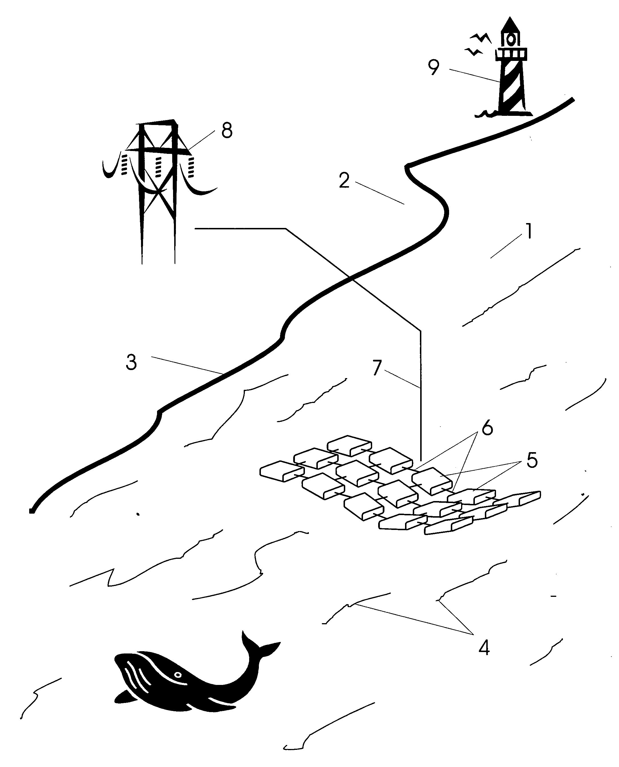
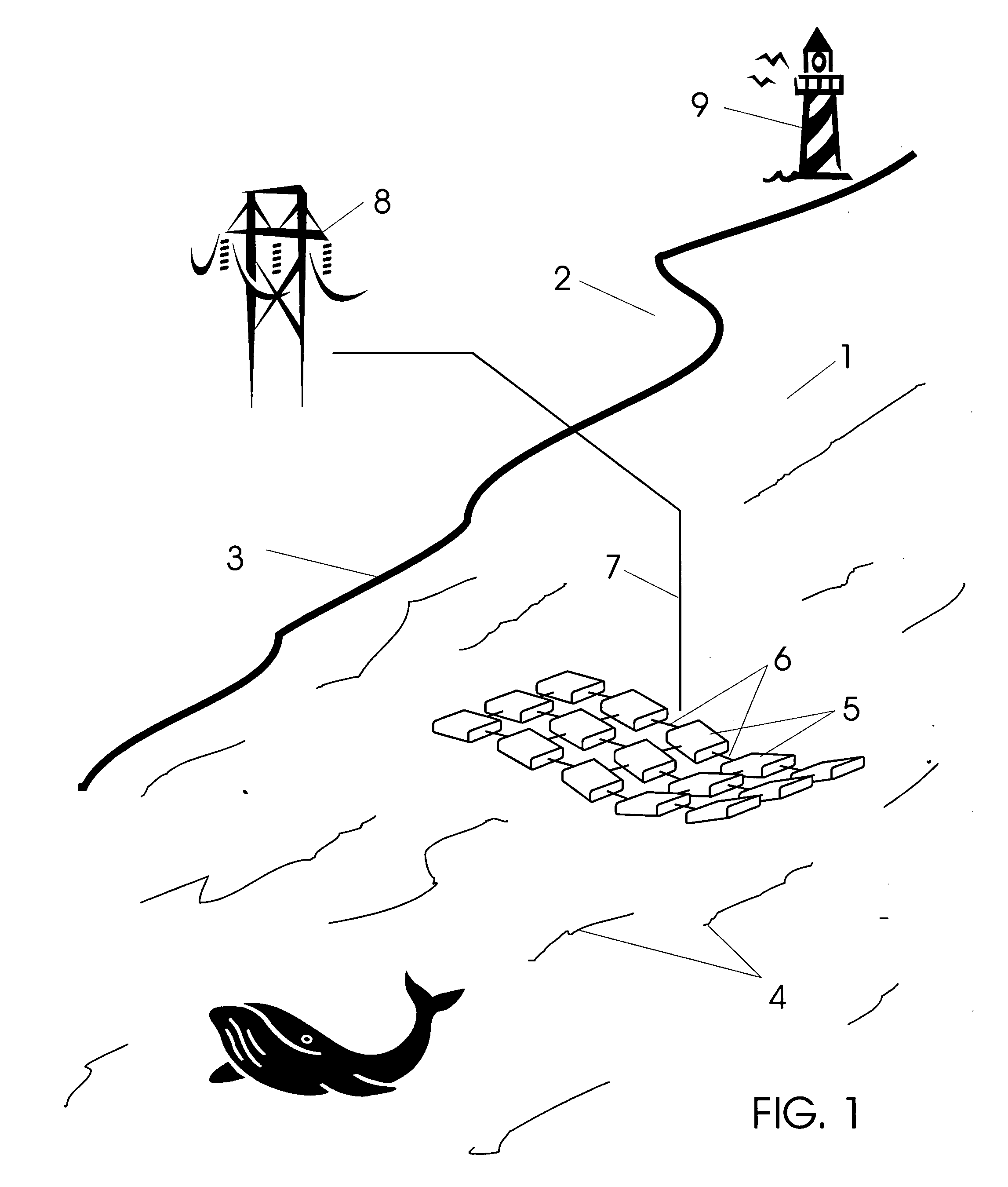
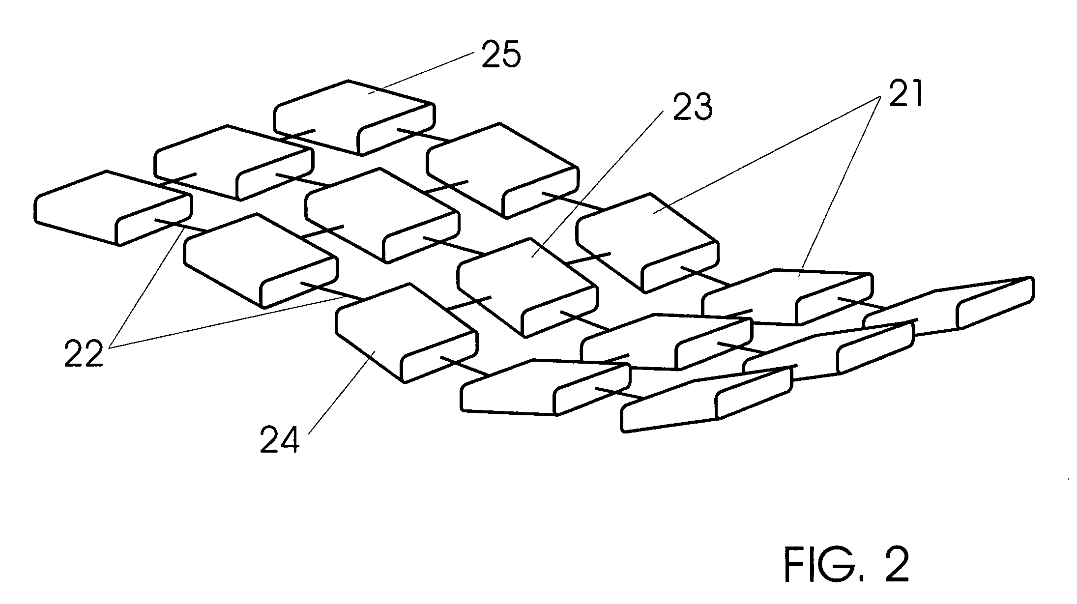
[0067]Wave energy converters are formed in accordance with the teaching as an array of point absorbers—or float members. Each float member is mechanically coupled to its neighbor(s) by way of a rigid link. A shaft extends between and passes through the hull of a float member at a pivot point. The pivot point permits rotational motion in two orthogonal dimensions such that the float member is permitted to heave, pitch, and roll under the influence of passing waves upon which they ride. Because the end of the link shaft is inside an enclosed space of the float member, it moves about relative to the axis of the float members; the tip lying within a spherical section at all times.

[0068]In most preferred embodiments, a link includes two ends—one each being coupled to a different float member. In this fashion, two float members are said to be ‘coupled neighbors’. Forces are conveyed to the interior of a float member by way of the rigid link shaft end. These forces may couple with and driv...


PUM


Abstract

Wave energy, converters are arranged as a plurality of coupled float members arranged in a two dimensional array. Link couplings between any float member and its neighbors drive a mechanical system to convert the disorganized motion due to heaving and bobbing of the float member on the ocean's surface into linear reciprocating motion in orthogonal directions. Such linear reciprocating motion is converted to electricity in an induction system having a mover and a stator—either being an inductor, the other being a magnet. The array is preferably provided to cover large surface areas whereby energy from incident ocean waves is appreciably absorbed at the float member an converted to mechanical motion. The array may be held to the ocean floor by a mooring or anchor system immediately offshore or up to a few tens of kilometers from the shoreline. Electricity provided at the array may be conveyed to shore via a submarine power transmission cable where it may be distributed and consumed on the public grid.

Description

BACKGROUND OF THE INVENTION[0001]1. Field[0002]The following invention disclosure is generally concerned with wave energy converters and more specifically concerned with wave energy converters having an array of float members coupled together.[0003]2. Prior Art[0004]Ocean wave energy converters, or ‘WECs’, convert the kinetic energy in ocean surface waves to electrical energy which is in high demand by most of modern societies. The entire energy demands of the world population is contained in a very small area of the ocean's surface. The total annual average energy off the United States coastlines has been estimated (Bedard et al. 2005) at 2,100 Terawatts-hours or 2.1×10¹⁵ Wh.[0005]Indeed, it is common to find an energy density of incoming ocean waves of up to 65 MW per mile of shoreline. Of course many authors have argued for considerably more by some calculations, but without consideration of the very high seas of Scotland or the Pacific Northwest of the United States, many calm o...

Claims


Application Information

Patent Timeline
Patent Type & Authority Applications(United States)
IPC IPC(8): F03B13/18
CPCF03B13/20F05B2220/7066F05B2240/40Y02E10/38H02K7/1876H02K16/00F05B2260/406Y02E10/30
Inventor PAGE, JOSEPH
Owner PAGE JOSEPH
Learn More