
Photoelectric conversion device, production method thereof, photosensor, imaging device and their drive methods

a technology of photoelectric conversion and production method, applied in the direction of triarylamine dye, anthracene dye, television system, etc., can solve the problems of large configuration restriction and increase of dark current causing noise, and achieve the effect of reducing the increase of dark current and low dark curren

Active Publication Date: 2011-03-17
FUJIFILM CORP
View PDF5 Cites 17 Cited by
  • Summary
  • Abstract
  • Description
  • Claims
  • Application Information

AI Technical Summary

Benefits of technology

[0027]The present invention has been made to solve these problems, and an object of the present invention is to provide a photoelectric conversion device capable of functioning as a photoelectric conversion device when applied to a photoelectric conversion device, exhibiting a low dark current and reducing the increase of dark current even when the device is heat-treated, and an imaging device equipped with such a photoelectric conversion device.
[0069]According to the present invention, a photoelectric conversion device capable of functioning as a photoelectric conversion device when a compound having a specific structure is applied to a photoelectric conversion device, exhibiting a low dark current and reducing the increase of dark current even when the device is heated, and an imaging device equipped with such a photoelectric conversion device, can be provided.

Problems solved by technology

That is, in the case of a photoelectric conversion device material having a diarylamine partial structure utilizing hole transport, the material needs to be designed to satisfy small Ea (electron affinity) value, high hole transportability and high heat resistance, and the configuration is greatly restricted so as to satisfy these requirements.
When a material with a small Ip (ionization potential) value and a material with a large Ea value (for example, fullerene C60) are contacted, an electric charge (electron, hole) is generated in LUMO of the material layer having a large Ea value from HOMO of the material layer having a small Ip value within the photoelectric conversion device due to thermal excitation, as a result, a dark current causing noise is increased.

Method used


Image

  • Photoelectric conversion device, production method thereof, photosensor, imaging device and their drive methods
  • Photoelectric conversion device, production method thereof, photosensor, imaging device and their drive methods
  • Photoelectric conversion device, production method thereof, photosensor, imaging device and their drive methods

Examples


example 1

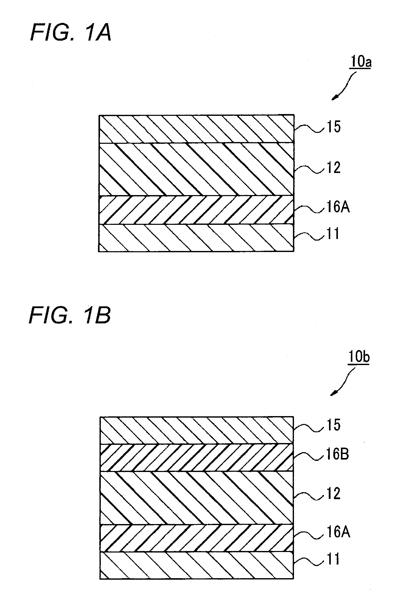
[0443]A photoelectric conversion device of the embodiment shown in FIG. 1A was fabricated. That is, amorphous ITO was deposited on a glass substrate by sputtering to a thickness of 30 nm, thereby forming a lower electrode, and Compound (a-2) was deposited thereon by using a mask by vacuum heating deposition to a thickness of 100 nm to form an electron blocking layer. Thereafter, a layer formed by co-depositing Compound (1) and fullerene (Co) to a thickness of 100 nm and 300 nm by using a mask, respectively, in terms of a single layer was deposited thereon by vacuum heating deposition in a state of the substrate temperature being controlled to 25° C. to form a photoelectric conversion layer. Here, the vacuum deposition of the photoelectric conversion layer was performed at a vacuum degree of 4×10⁻⁴ Pa or less.

[0444]Furthermore, amorphous ITO was deposited thereon as an upper electrode by sputtering to a thickness of 10 nm by using a mask to form a transparent electrode. In this way, ...

example 2

[0446]A photoelectric conversion device was fabricated in the same manner except that in Example 1, the film thickness of Compound (1) was changed to 30 nm.


PUM

PropertyMeasurementUnit
ionization potentialaaaaaaaaaa
voltageaaaaaaaaaa

Abstract

A photoelectric conversion device comprising a transparent electrically conductive film, a photoelectric conversion film and an electrically conductive film in this order, wherein the photoelectric conversion film comprises a photoelectric conversion layer, and an electron blocking layer, wherein the electron blocking layer contains a compound represented by the specific formula.

Description

BACKGROUND OF THE INVENTION[0001]1. Field of the Invention[0002]The present invention relates to a photoelectric conversion device, a production method thereof, a photosensor, an imaging device and their driving methods.[0003]2. Description of the Related Art[0004]As for the solid-state imaging device, there is widely used a flat light-receiving device where photoelectric conversion sites are two-dimensionally arrayed in a semiconductor to form pixels and a signal generated by photoelectric conversion in each pixel is charge-transferred and read out through a CCD or CMOS circuit. The conventional photoelectric conversion site generally used is a photodiode part formed using PN junction in a semiconductor such as Si.[0005]In recent years, fabrication of a multipixel device is proceeding, and the pixel size and in turn, the area of a photodiode part become small, which brings about problems of reduction in the aperture ratio, reduction in the light collection efficiency and the result...

Claims


Application Information

Patent Timeline
Patent Type & Authority Applications(United States)
IPC IPC(8): H04N5/335H01L51/54H01L51/56C07D403/10C07D401/10C07C211/61H10K99/00
CPCB82Y10/00H01L51/0046H01L51/0059H01L51/0067H01L51/0069Y02E10/549H01L51/4253H01L51/005H01L51/0052H01L51/0071H01L51/0072H01L51/0094C09B23/04C09B57/008C09B57/10H10K85/211H10K85/656H10K85/631H10K85/654H10K85/40H10K30/30H10K39/32H01L31/041C07C211/61C07D403/10H01L31/04H10K85/6572H10K85/60H10K85/615H10K85/657
Inventor NOMURA, KIMIATSUFUKUZAKI, EIJIMITSUI, TETSURO
Owner FUJIFILM CORP
Features
  • Generate Ideas
  • Intellectual Property
  • Life Sciences
  • Materials
  • Tech Scout
  • Unparalleled Data Quality
  • Higher Quality Content
  • 60% Fewer Hallucinations
Learn More