Intracranial pressure sensor

a technology of intracranial pressure and sensor, which is applied in the field of physiological measurements, can solve the problems of limited useful life, head injury, and the typical use of neurosurgical intracranial monitors, and achieve the effects of convenient implanting of intracranial pressure monitoring systems, reducing the need for batteries, and reducing the need for energy transducers

Inactive Publication Date: 2011-03-17
DREXEL UNIV
View PDF16 Cites 46 Cited by
  • Summary
  • Abstract
  • Description
  • Claims
  • Application Information

AI Technical Summary

Benefits of technology

[0032]The sensor can be attached to a probe-like extension that can extend from the vicinity of the scalp or the skull, through an opening in the skull, through the dura, and down to the level of the CSF. The probe can include a pressure sensor attached thereto and positioned to communicate directly with the CSF. The subdural sensor of the invention can thus directly sense the pressure of the CSF. Accordingly, the subdural sensor can provide a direct reading of the pressure of the CSF. A housing, such as a disc shaped housing, can contain the other elements of the intracranial pressure monitoring system, such as the battery and the electronics, and any other required components. The housing can be placed outside the skull, immediately below the scalp. In an alternate embodiment the housing can be place outside the scalp. The opening extending from the housing to the CSF can be very narrow, since it only needs to accommodate the sensor and the probe. For example, a diameter of 2-4 mm can be more than sufficient. The fact that only a very narrow opening through the skull and dura is required, and that only the probe needs to be extended through the opening, facilitates implanting the intracranial pressure monitoring system under adverse conditions.
[0033]Additionally, a bat

Problems solved by technology

However, existing neurosurgical intracranial monitors can typically be implanted and used only in hospital settings, most typically in operating rooms or intensive care units, and have limited useful life due to drift, infection and other factors.
Stroke is the third leading cause of death in the United States, and head injury is a leading cause of death in adolescents and young adults.
Since the skull forms an almost complete rigid container for the brain, measuring intracranial pressure directly can be very difficult.
However, penetration of the skull to insert a pressure sensor requires a neurosurgical procedure with significant risks.
Existing neurosurgical intracranial pressure monitors could only be used in the hospital setting, and have limited useful life due to drift and infection.
However, devices with significant inductive or magnetic components, including radio frequency circuit-based devices, were not compatible with magnetic resonance imaging, a procedure often critical to management of patients with abnormal intracranial pressure.
Further, many of these devices had a limited lifetime, particularly devices with plastic components, which age rapidly in vivo when in contact with extracellular space, or slide bearings, which are not reliable over long term.
For example, a device relying on measurement via a flexible diaphragm could become useless if encased in relatively stiffer scar tissue while a device requiring CSF flow could become prone to clogging in many cases.
In addition, many of these devices required either a large number of parts, precise machining or rare and/or exotic materials making manufacture and assembly c

Method used


Image

  • Intracranial pressure sensor
  • Intracranial pressure sensor
  • Intracranial pressure sensor

Examples


Embodiment Construction

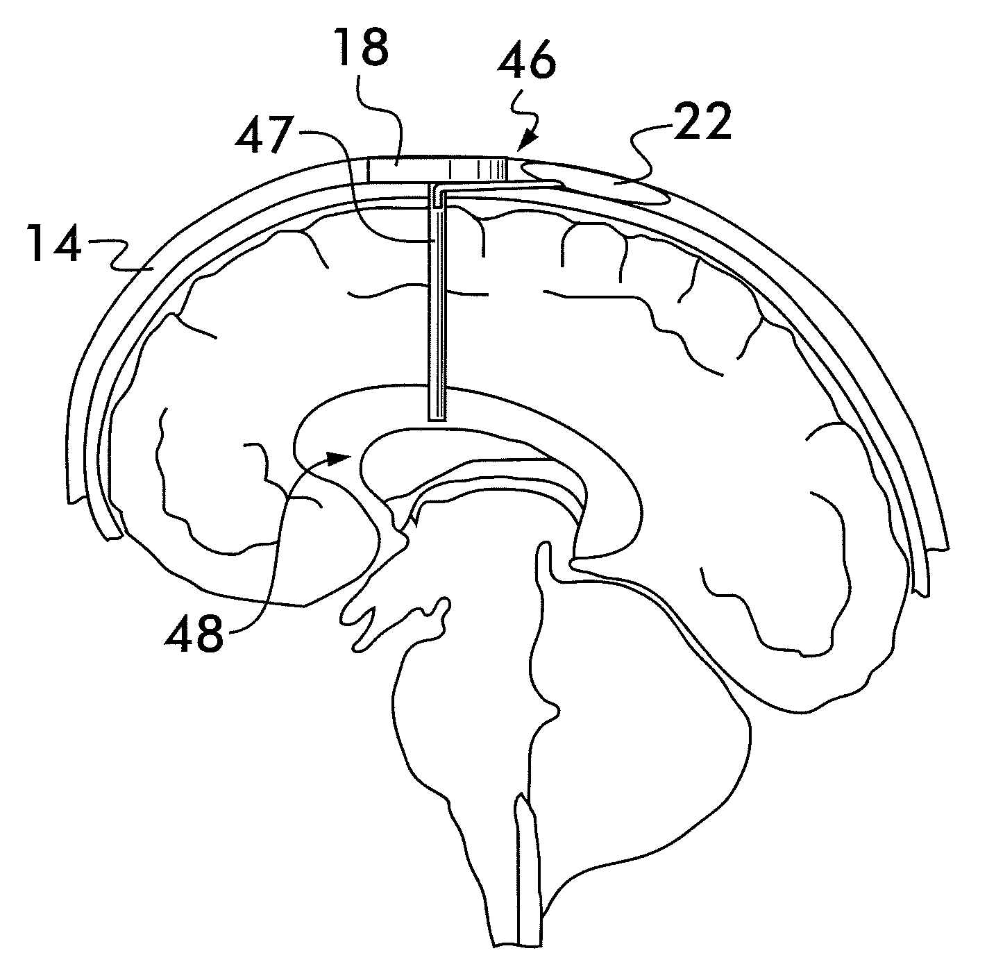
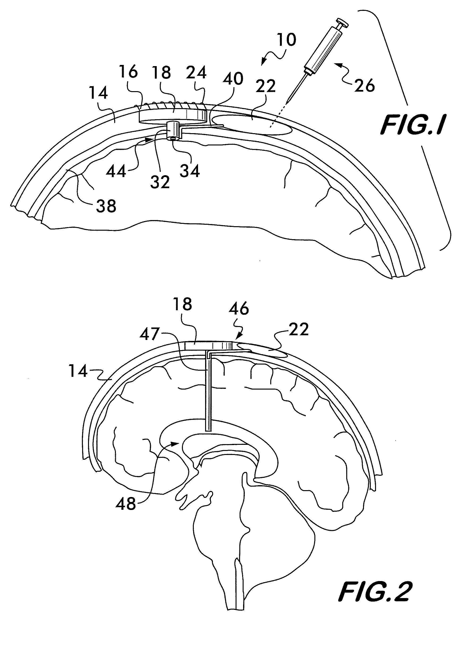
[0046]Referring now to FIG. 1, there is shown an embodiment of the intracranial pressure monitor system 10 of the invention. The intracranial pressure monitor system 10 includes a housing portion 18, which can contain a portion of the circuitry required for monitoring the pressure of the CSF within a skull 14. The circuitry within the housing portion 18 of the intracranial pressure system 10 can be substantially similar to the circuitry disclosed in U.S. Pat. Pub. No. 2009 / 0216149, entitled “Self-Contained, Implantable, Intracranial Pressure Sensing Device and Methods For Its Use In Monitoring Intracranial Pressure,” published Aug. 27, 2009, which is incorporated by reference in its entirety. In a preferred embodiment of the invention, the housing portion 18 can be located between the scalp 16 and the skull 14, with the bottom surface of the housing portion 18 resting on the outer surface of the skull 14. In another embodiment, the bottom surface of the housing portion 18 can rest o...


PUM


Abstract

An intracranial pressure device for measuring CSF pressure in a skull includes a housing located between the scalp and the skull containing pressure device circuitry and a conduit extending downwardly from the housing to the vicinity of the CSF. A pressure sensor is coupled to the conduit and located in communication with the CSF wherein the pressure sensor directly senses the pressure of the CSF and provides a signal representative of the pressure of the CSF to the pressure device circuitry by way of the conduit. The skull has a dura and the conduit extends by way of an opening through the skull and an opening through the dura to position the sensor in direct contact with the CSF. A fluid reservoir can be in communication with the CSF by way of a tube and by way of the housing. The fluid reservoir contains CSF.

Description

STATEMENT REGARDING FEDERALLY SPONSORED RESEARCH OR DEVELOPMENT[0001]This invention was supported in part by funds from the U.S. government (NIH Grant R21 NS050590-01). The U.S. government may therefore have certain rights in the invention.FIELD OF INVENTION[0002]This invention relates to the field of physiological measurements and, in particular, to a system for measuring the presence of a fluid.DESCRIPTION OF RELATED ART[0003]The final common pathway for death and permanent disability in head injuries and brain disease is usually increased intracranial pressure. For this reason, measurement and control of intracranial pressure is a major focus of care in these cases, both acutely and chronically. It is known in the art to provide microelectromechanical (MEMS) based microwave intracranial pressure sensing devices which allow for non-invasive monitoring of intracranial pressure when used with a portable microwave monitor. Such devices are useful in several areas. However, existing n...

Claims


Application Information

Patent Timeline
IPC IPC(8): A61B5/03A61M1/00
CPCA61B5/031
Inventor KAWOOS, USMAHROSEN, ARYEROSEN, HAREL D.KRALICK, FRANCIS A.
Owner DREXEL UNIV
Why Eureka
Try Eureka