Air-conditioning device for vehicle

a technology for air conditioning devices and vehicles, which is applied in the direction of domestic cooling devices, lighting and heating devices, and cooling fluid circulation, etc. it can solve the problems of insufficient inability to complete condensation water regeneration, and inability to use extra power and commercials to eliminate odors, etc., to achieve the effect of reducing mileage, reducing fuel consumption of vehicles, and reducing fuel consumption

Inactive Publication Date: 2011-03-24
DENSO CORP
View PDF11 Cites 64 Cited by
  • Summary
  • Abstract
  • Description
  • Claims
  • Application Information

AI Technical Summary

Benefits of technology

In view of the foregoing and other problems, it is a first object of the present invention to provide an air-conditioning device to restrict odor generation and bacteria growth at air-conditioning start time by drying an indoor heat exchanger with preventing a battery death while a vehicle is parked.
When it is not raining, the target blow-off temperature of the evaporator is raised, and the frequency for outputting the operation request signal to the engine controller is lowered. Therefore, fuel consumption of the vehicle can be sufficiently reduced as a whole. At this time, the inlet air temperature of the heater is raised by raising the target blow-off temperature of the evaporator. Even if the temperature of the cooling water supplied to the heater is lowered by lowering the operation frequency of the engine, conditioned air having a predetermined temperature can be produced. As a result, heating operation can be performed with reducing mileage deterioration. Further, when it is not raining, a temperature of window glass is difficult to be lowered. Therefore, fogging resistance property can be secured for the window glass even if the target blow-off temperature of the evaporator is raised.

Problems solved by technology

That is, in the conventional air-conditioning device, the regeneration of condensation water may not be completed even if the compressor is reactivated, in a case where conditioned-air is sent into the passenger compartment by a blower in response to an air-conditioning start signal in a driving time.
In this case, air containing moisture with bad smell may be blown into the passenger compartment in early stage of the air-conditioning.
However, the extra power and the commercial are not used for eliminating the odor.
However, in the conventional air-conditioning device, in a case where conditioned-air is sent into the passenger compartment by a blower in response to an air-conditioning start signal in a driving time, the regeneration of condensation water may not be completed, even if the compressor is reactivated.
In this case, air containing moisture with bad smell may be blown into the passenger compartment in early stage of the air-conditioning.
Further, effect of reducing fuel consumption may not be obtained, since it is necessary to operate the engine.
Since air flows from front to rear in the passenger compartment, air cooled by the front windshield will hit a face part of occupant, such that the occupant may feel uncomfortable.
In this case, the effect of reducing fuel consumption may not be obtained.

Method used


Image

  • Air-conditioning device for vehicle
  • Air-conditioning device for vehicle
  • Air-conditioning device for vehicle

Examples


first embodiment

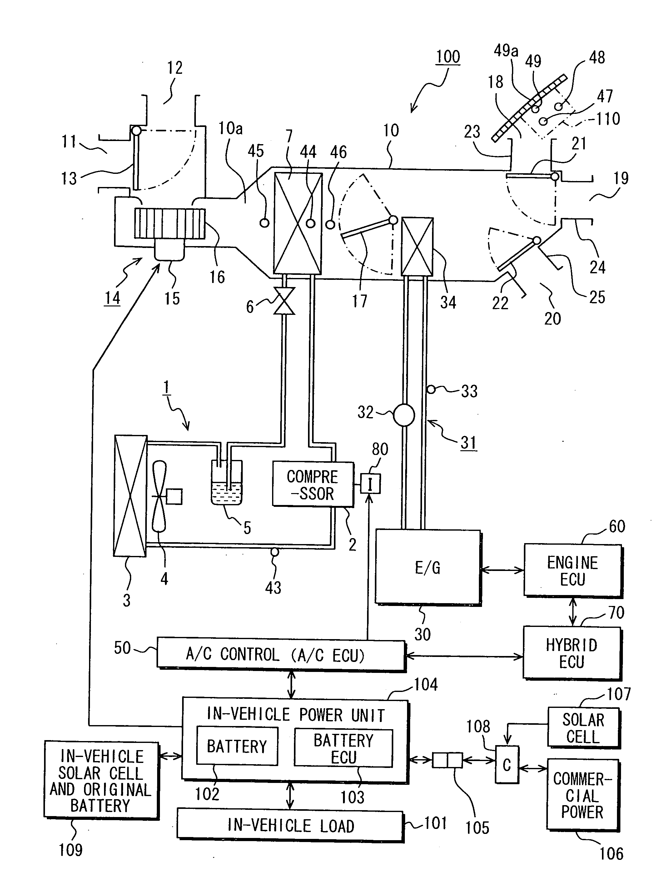
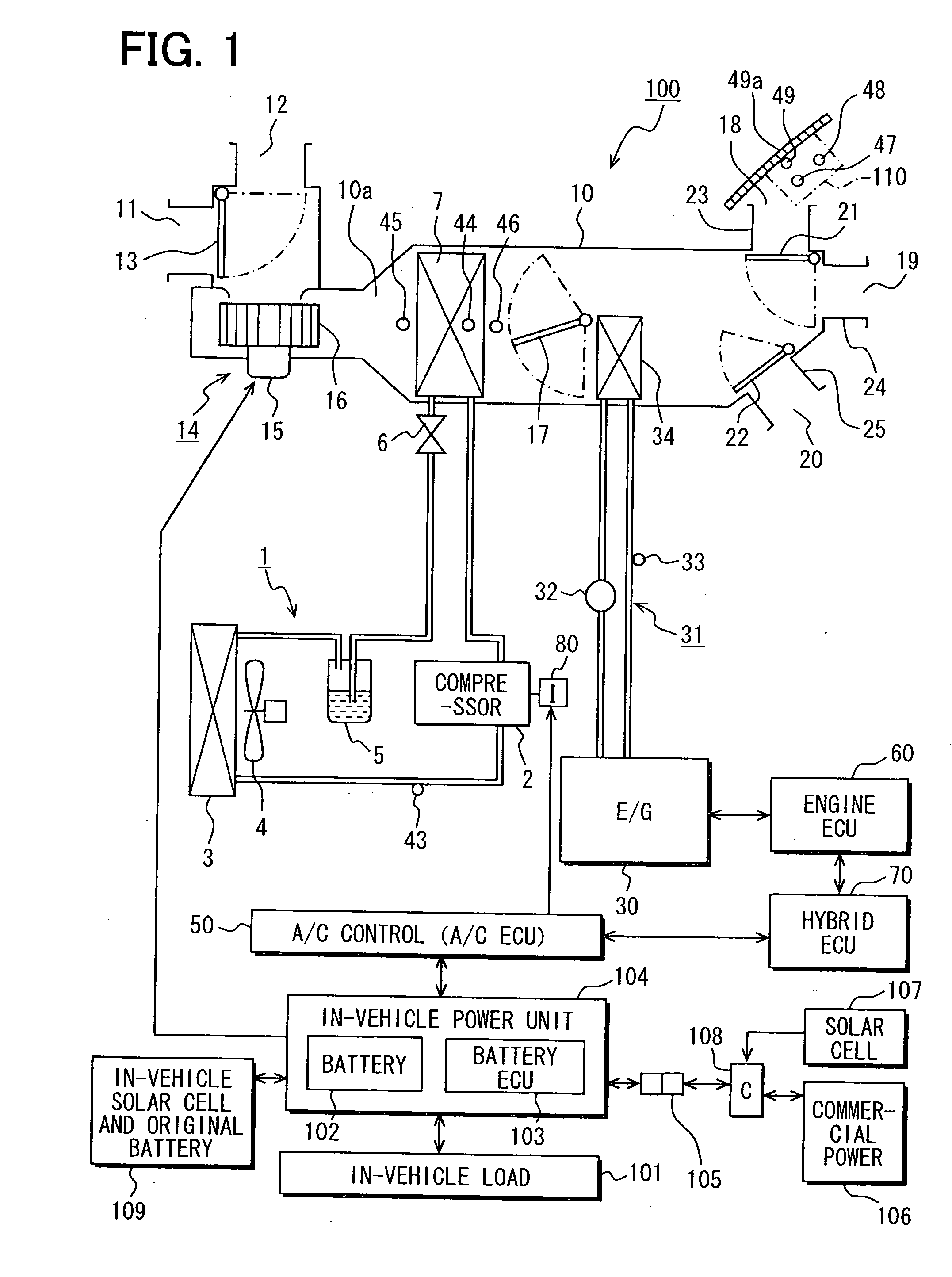
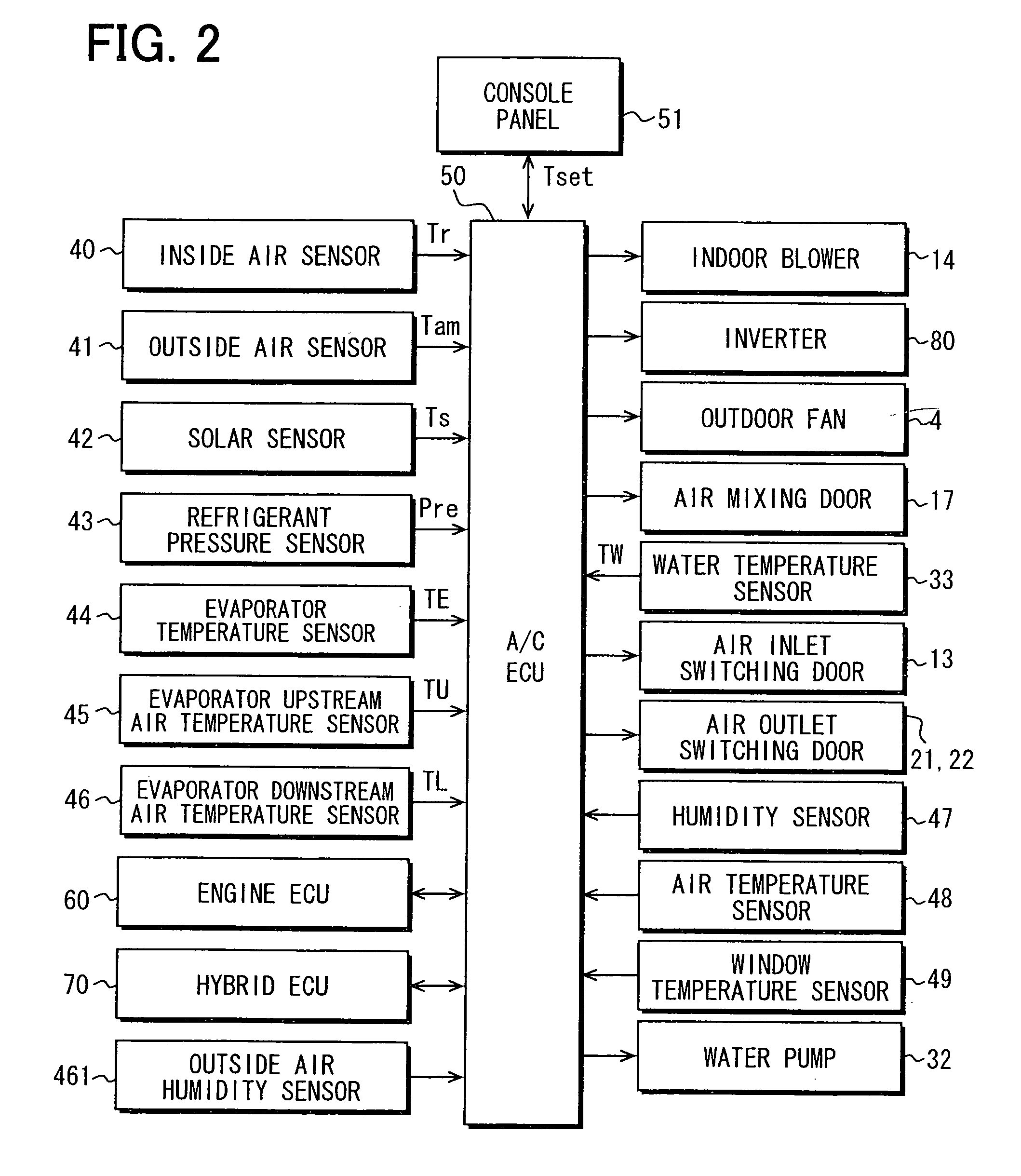
A first embodiment will be described with reference to FIGS. 1-6. An air-conditioning device 100 of FIG. 1 is used for a hybrid car in the first embodiment. FIG. 1 is a schematic diagram illustrating the air-conditioning device 100 and its power-source system. FIG. 2 is a block diagram illustrating peripherals of an air-conditioning control device of the air-conditioning device 100.

The hybrid car has an engine 30, an in-vehicle load 101, an engine electronic control device 60 (hereinafter referred as engine ECU 60), and a battery 102. The engine 30 generates power by combusting liquid fuel such as gasoline. The in-vehicle load 101 has motor function and generator function for assisting a driving of the car, and includes a non-illustrated drive-assisting motor generator. The engine ECU 60 controls fuel supply amount and ignition timing for the engine 30, for example. The battery 102 supplies electric power for the motor generator of the in-vehicle load 101, and the engine ECU 60, for...

second embodiment

Evaporation heat is emitted from the evaporator 7 of FIG. 1 while the condensation water is evaporated in the drying control of the evaporator 7, such that temperatures of the evaporator 7 and air downstream of the evaporator 7 are lowered. After the drying control is finished, the temperature of the air downstream of the evaporator 7 is raised to an approximately the same temperature as that of air upstream of the evaporator 7. Therefore, the finishing of the drying control of the evaporator 7 can be judged by this phenomenon.

In a second embodiment, the air-conditioning ECU 50 uses a temperature of a predetermined position of the evaporator 7 so as to judge a dryness degree of the evaporator 7. The dryness degree of the evaporator 7 is judged using a directly-detected temperature value of the evaporator 7 or around the evaporator 7.

Therefore, odor generated at a start time of air-conditioning can be properly prevented. The second embodiment will be described with reference to FIG. ...

third embodiment

In a third embodiment, the drying operation of the evaporator 7 of FIG. 1 is performed in a case where there is sufficient amount of electric power remained in the battery 102 or the original battery of the in-vehicle solar cell 109. An electronic control unit corresponding to the battery ECU 103 to control the in-vehicle battery 102 of FIG. 1 is mounted to an electric car or a hybrid car. The electronic control unit manages charge and discharge of the battery 102 and the original battery. In the third embodiment, information of battery residual quantity provided from the battery ECU 103 is used.

FIG. 8 is a flow chart showing details of blower voltage determination and evaporator dry control of the third embodiment. S80, S82, S83, S85 and S81 of FIG. 8 are similar to S40, S42, S43, S45 and S41 of FIG. 4.

At S84, the information of battery residual quantity is input from, the battery ECU 103 of FIG. 1 into the air-conditioning control device (air-conditioning ECU) 50 through multiplex...


PUM


Abstract

An air-conditioning device for a vehicle includes a blower and an estimating portion. The blower is disposed in an air-conditioning case, and performs a dry control for a heat exchanger arranged in a passenger compartment of the vehicle by sending air. The blower uses one of power supplied from an external power source, power supplied from the battery having residual quantity equal to or larger than a predetermined quantity, or power supplied from an in-vehicle solar cell, while the vehicle is parked. The estimating portion estimates an approximate elimination of odor generated from the heat exchanger by starting the sending of air, and stops the blower based on the estimation.

Description

CROSS REFERENCE TO RELATED APPLICATIONThis application is based on Japanese Patent Application No. 2009-218235 filed on Sep. 21, 2009, Japanese Patent Application No. 2009-218236 filed on Sep. 21, 2009, and Japanese Patent Application No. 2009-218269 filed on Sep. 22, 2009, the disclosures of which are incorporated herein by reference in their entirety.BACKGROUND OF THE INVENTIONThe present invention relates to an air-conditioning device for a vehicle.JP-A-2001-130247 discloses an air-conditioning device for a vehicle, in which a temperature of an evaporator is controlled in a predetermined range so as to prevent odor generated by drying. Due to the preventing of the odor generation, power can be saved for a compressor driving source such as an engine of the vehicle, and occupant comfortableness can be raised.According to JP-A-2001-130247, the odor is generated in air to be blown out of the evaporator. The odor generation is started when adhering odor component is separated from a f...

Claims


Application Information

Patent Timeline
Patent Type & Authority Applications(United States)
IPC IPC(8): F25B49/00
CPCB60H3/0085
Inventor ICHISHI, YOSHINORIYANAGIMACHI, YOSHINORIKONDO, YASUSHIKAWASHIMA, MASAFUMIMISUMI, HARUKI
Owner DENSO CORP
Why Eureka
Try Eureka