Light source unit, projection apparatus, and projection method

a technology of projection apparatus and light source unit, which is applied in the direction of static indicating device, picture reproducer, instruments, etc., can solve the problem of reducing the luminous efficiency of fluorescent substances, and achieve the effect of increasing the luminous efficiency

Active Publication Date: 2011-03-31
CASIO COMPUTER CO LTD
View PDF3 Cites 57 Cited by
  • Summary
  • Abstract
  • Description
  • Claims
  • Application Information

AI Technical Summary

Benefits of technology

[0012]According to one aspect of the present invention, there is provided a projection apparatus comprising: a first light source configured to emit light in a first wavelength range; a light-source light generator configured to generate light-source light of two or more colors with different luminous efficiencies by time-sharing by using the light emitted from the first light source; a second light source configured to emit light in a second wavelength range different from the first wavelength range; a light source controller configured to control timings of driving the first and second light sources and the light-source light generator, so that the light-source light of two or more colors generated by the light-source light generator and the light-source light emitted from the second light source are cyclically generated, by setting a light-emitting period of at least one light-source light color having a higher luminous efficiency out of the two or more colors generated by the light-source light generator, shorter than those of the other light-source light colors, and setting a drive power of the first light source during generation of the light-source light color whose light-emitting period is set short, greater than a drive power of the first light source during generation of the other light-source light colors; an input unit configured to input an image signal; and a projector configured to form a light figure of colors corresponding to an image signal input from the input unit, by using the light-source light generated based on the control of the light source controller, and to project the light figure.

Problems solved by technology

Therefore, there is a problem that the absolute quantity of light becomes insufficient if excitation light is decreased to avoid saturation of the fluorescent substance, and the luminous efficiency of the fluorescent substance is decreased if excitation light is increased to obtain a sufficient absolute light quantity.

Method used


Image

  • Light source unit, projection apparatus, and projection method
  • Light source unit, projection apparatus, and projection method
  • Light source unit, projection apparatus, and projection method

Examples


first embodiment

[0027]A first embodiment applied to a DLP (a registered trademark) type data projector will be described with reference to the drawings.

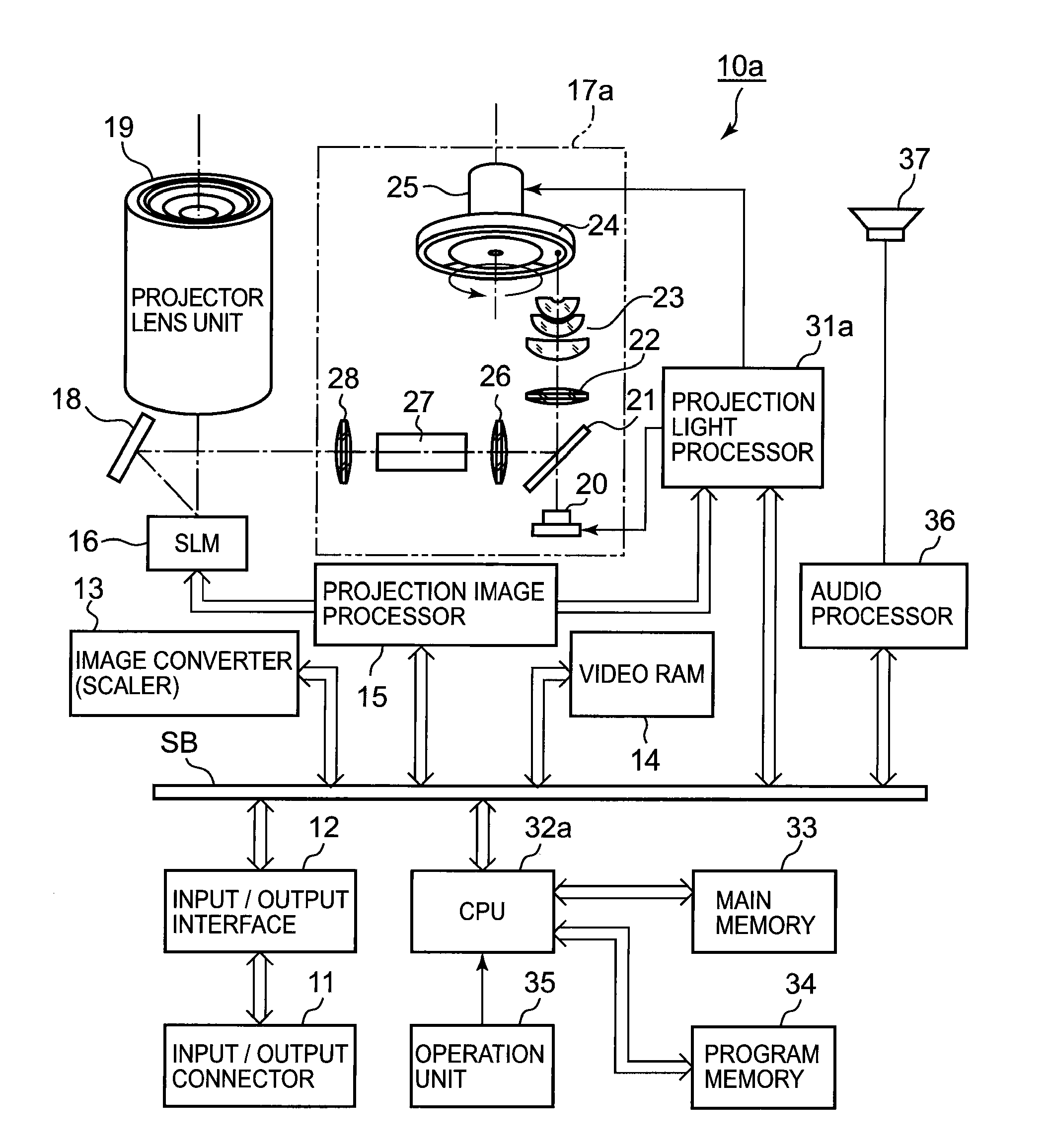
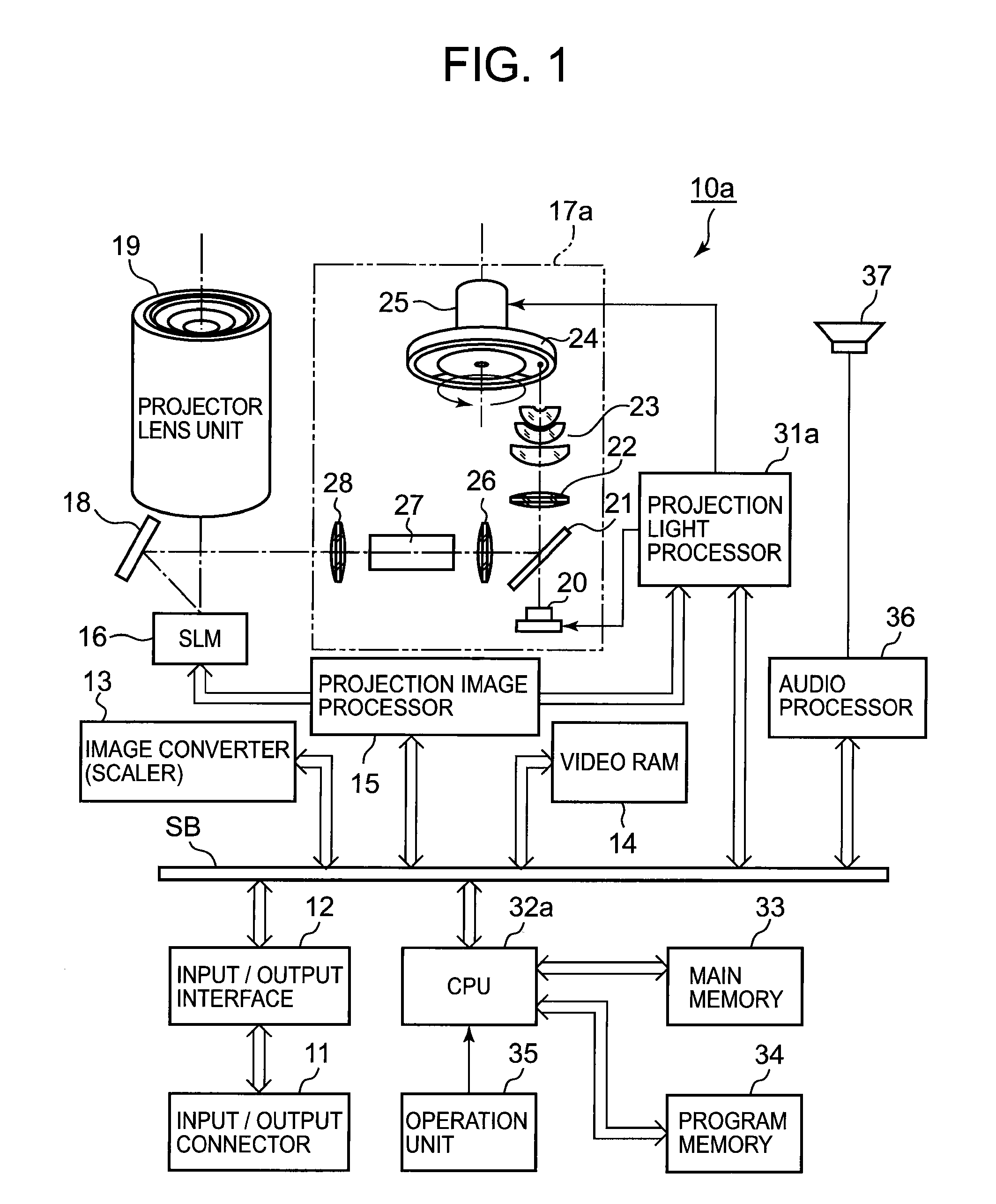
[0028]FIG. 1 is a block diagram showing a schematic functional configuration of electronic circuits provided in a data projector 10a according to the first embodiment.

[0029]A reference number 11 denotes an input / output connector, which includes a pin-jack (RCA) type video input terminal, D-sub 15 type RGB input terminal, and Universal Serial Bus (USB) connector, for example.

[0030]Image signals of various standards input to the input / output connector 11 are applied to an image converter 13 through an input / output interface (I / F) 12 and a system bus SB.

[0031]The image converter 13 converts the input image signal into a predetermined format suitable for projection, writes the image signal into a video RAM 14 or a buffer memory for display if necessary, reads the written image signal, and transmits the read image signal to a projection image processor 1...

second embodiment

[0071]A second embodiment applied to a DLP (a registered trademark) type data projector will be described with reference to the drawings.

[0072]FIG. 4 is a block diagram showing a schematic functional configuration of electronic circuits provided in a data projector 10b according to the second embodiment.

[0073]The configuration is substantially the same as that shown in FIG. 1, except for a light source unit 17b instead of 17a, a projection light processor 31b controlling the light source unit 17b, and a CPU 32b. The same components are denoted by the same reference numbers, and an explanation thereof will be omitted.

[0074]The light source unit 17b has two kinds of light sources; a semiconductor laser 41 emitting blue laser light, and an LED 42 emitting red light.

[0075]The blue laser light emitted from the semiconductor laser 41 is reflected on a mirror 43, transmitted through a dichroic mirror 44, and applied at one point on the surface of a color wheel 45. The color wheel 45 is rot...


PUM


Abstract

A light source controller is configured to control timings of driving the first and second light sources and the light-source light generator, so that the light-source light of two or more colors generated by the light-source light generator and the light-source light emitted from the second light source are cyclically generated, by setting a light-emitting period of at least one light-source light color having a higher luminous efficiency out of the two or more colors generated by the light-source light generator, shorter than those of the other light-source light colors, and setting a drive power of the first light source during generation of the light-source light color whose light-emitting period is set short, greater than a drive power of the first light source during generation of the other light-source light colors.

Description

CROSS-REFERENCE TO RELATED APPLICATIONS[0001]This application is based upon and claims the benefit of priority from prior Japanese Patent Application No. 2009-223333, filed Sep. 28, 2009, the entire contents of which are incorporated herein by reference.BACKGROUND OF THE INVENTION[0002]1. Field of the Invention[0003]The present invention relates to a light source unit, a projection apparatus, and a projection method suitable for a projector or the like.[0004]2. Description of the Related Art[0005]Jpn. Pat. Appln. KOKAI Publication No. 2004-341105 (hereinafter, Patent Document 1), for example, discloses a technique including a light-emitting diode or semiconductor laser to emit ultraviolet light, and a color wheel which has a fluorescent layer formed on the back side for emitting visible light corresponding to each of red, green, and blue light by radiating ultraviolet light and has a visible light reflection film formed on the front side close to a light source, having characteristi...

Claims


Application Information

Patent Timeline
Patent Type & Authority Applications(United States)
IPC IPC(8): G03B21/14H05B37/02
CPCG03B21/204G03B21/14G03B33/08
Inventor OGAWA, MASAHIROSHIBASAKI, MAMORU
Owner CASIO COMPUTER CO LTD
Why Eureka
Try Eureka