
Method for manufacturing electrode, and method for manufacturing power storage device and power generation and storage device having the electrode

Inactive Publication Date: 2011-03-31
SEMICON ENERGY LAB CO LTD
View PDF8 Cites 5 Cited by
  • Summary
  • Abstract
  • Description
  • Claims
  • Application Information

AI Technical Summary

Benefits of technology

[0009]According to one embodiment of the present invention, it is an object to improve characteristics and extend a lifetime of a power storage device by making it possible to expand the volume in an electrode of the power storage device.
[0015]By obtaining an electrode in which the volume can be expanded, characteristics of a power storage device is improved and a lifetime thereof can be extended.

Problems solved by technology

However, in the case where silicon or the like is used for an electrode of a lithium ion battery, volume expansion in the electrode becomes a problem in some cases.
The volume expansion in the electrode causes deterioration in characteristics of the electrode and leads to reduction in yield and reliability.

Method used


Image

  • Method for manufacturing electrode, and method for manufacturing power storage device and power generation and storage device having the electrode
  • Method for manufacturing electrode, and method for manufacturing power storage device and power generation and storage device having the electrode
  • Method for manufacturing electrode, and method for manufacturing power storage device and power generation and storage device having the electrode

Examples


embodiment 1

[0027]In this embodiment, a battery according to one embodiment of the present invention and an electrode which can be applied to the battery will be described.

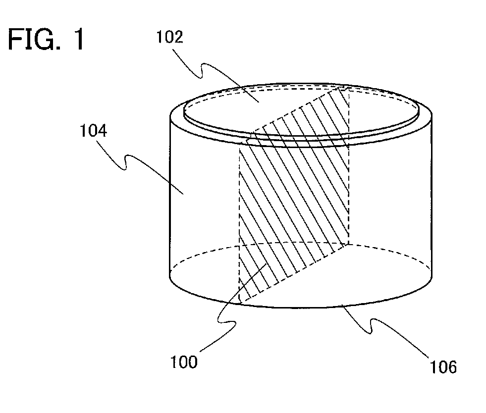
[0028]FIG. 1 is a perspective view illustrating an example of a cylindrical rechargeable battery according to one embodiment of the present invention. Note that the rechargeable battery according to one embodiment of the present invention is not limited to the cylindrical rechargeable battery, and may be a square rechargeable battery.

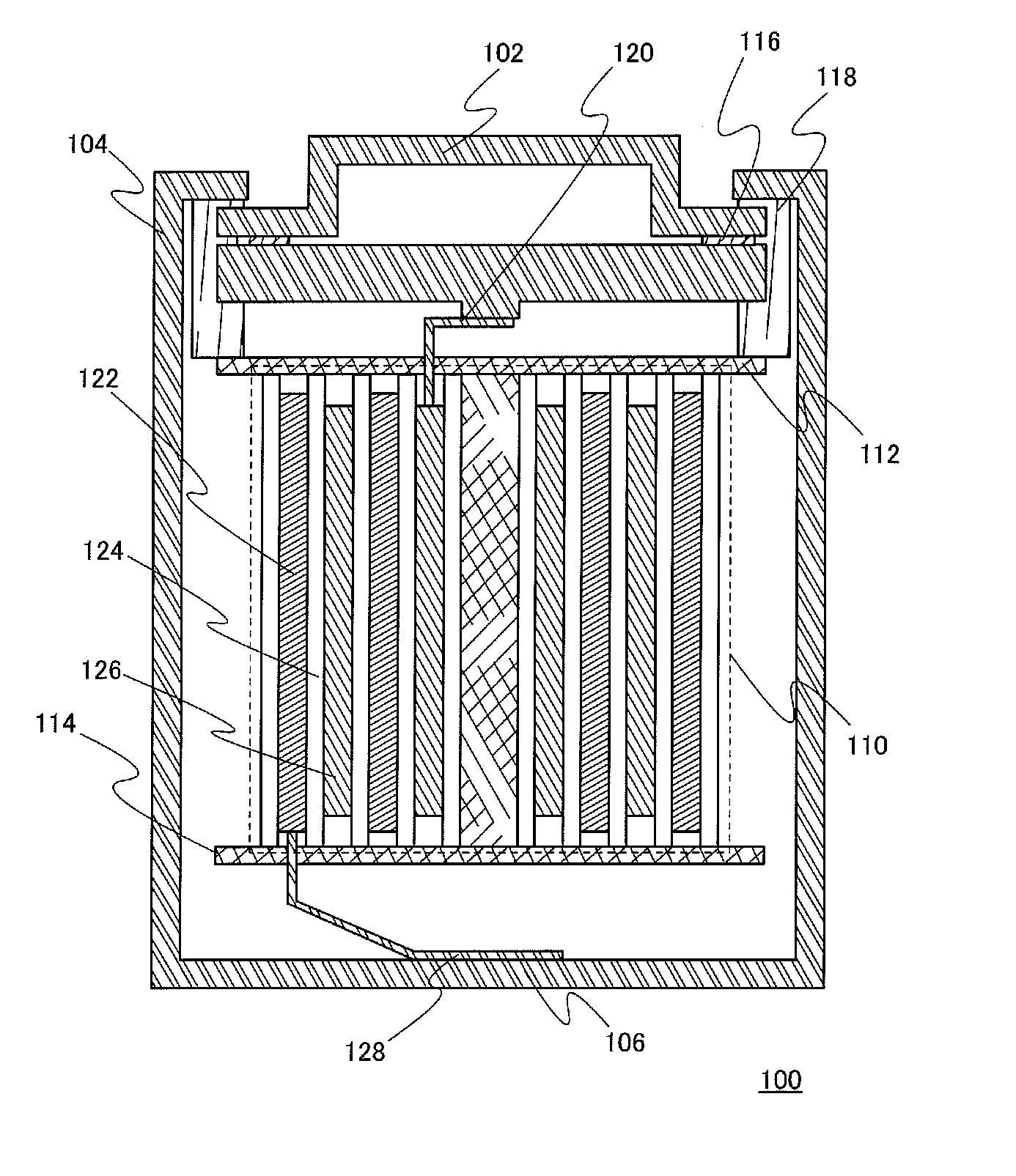
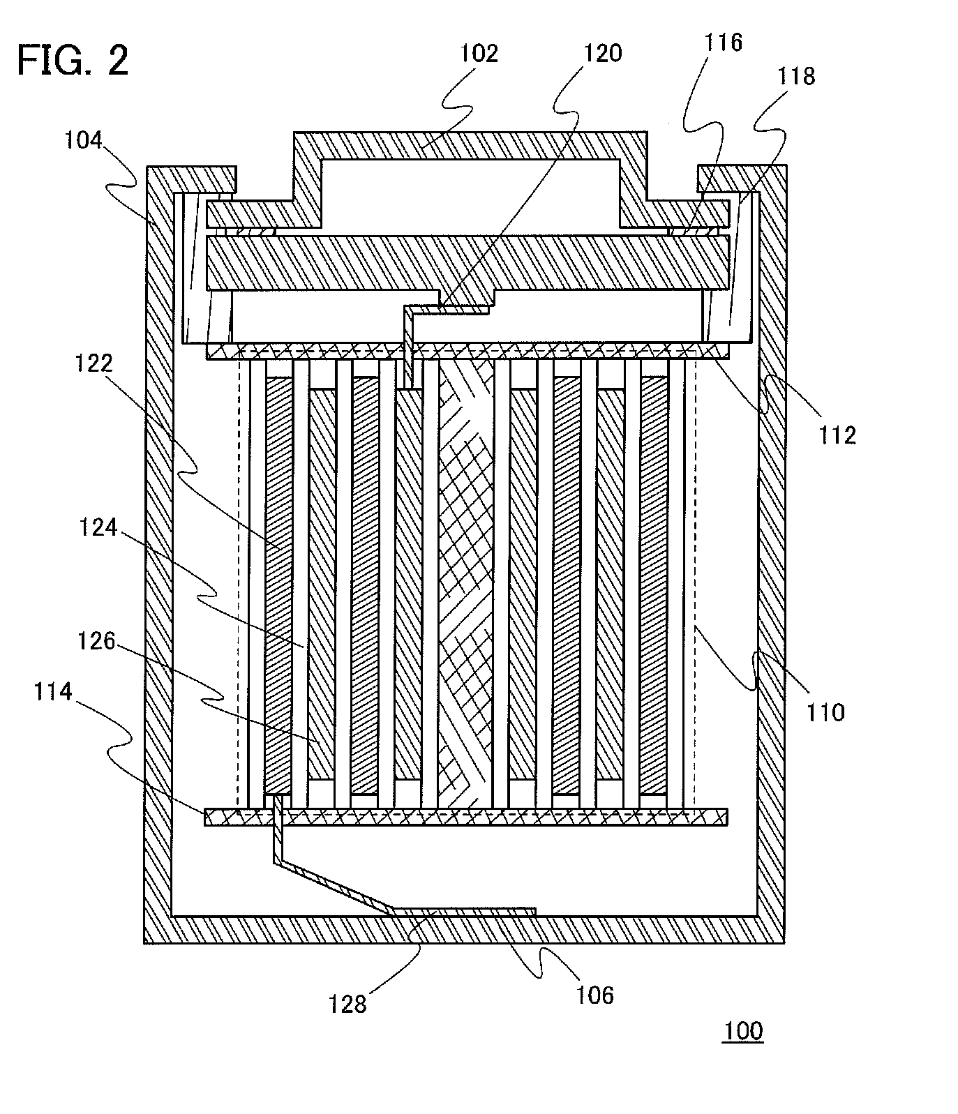
[0029]The cylindrical rechargeable battery in FIG. 1 has a closed space surrounded by a battery sidewall 104, a battery cover 102, and a battery bottom 106.

[0030]FIG. 2 is a cross-sectional view taken along a cross section 100 of the cylindrical rechargeable battery in FIG. 1.

[0031]The battery sidewall 104 and the battery bottom 106 may be formed using conductive materials, and a material which has sufficient mechanical strength and chemical resistance in an usage environment may be selected. As ...

embodiment 2

[0091]In this embodiment, a capacitor of one embodiment of the present invention will be explained.

[0092]In FIGS. 7A and 7B, a cross-sectional view (FIG. 7A) and a top view (FIG. 7B) of an example of the capacitor of one embodiment of the present invention is illustrated. In the capacitor illustrated in FIGS. 7A and 7B, an electrode 220 is interposed between a bottom cover 200 and a top cover 210, and the electrode 220 is provided in a closed space formed by the bottom cover 200, the top cover 210 and a gasket 208. Note that in FIGS. 7A and 7B, an example of cylindrical capacitor is described; however, the capacitor of one embodiment of the present invention is not limited thereto and the capacitor may be a square shape.

[0093]The electrode 220 includes a positive electrode 202, a negative electrode 204, and a separator 206 interposed therebetween. The positive electrode 202 includes a positive electrode current collector 212 and a positive electrode active material layer 214. The ne...


PUM


Abstract

The characteristics of a power storage device are improved and the lifetime of the power storage device is prolonged. An electrode is manufactured through the following steps: a step of forming an electrode film; a step of forming a damage layer by ion doping on the electrode film; and a step of providing a damage region between the damage layer and a surface. Alkali ion insertion and extraction can be performed by dipping of an electrode, in which the damage layer and the damage region are formed, in a solution containing an alkali ion. A space in which the volume of the electrode is expanded can be secured by the formation of the damage layer and the damage region. Note that another lithium may be used instead of an alkali metal.

Description

BACKGROUND OF THE INVENTION[0001]1. Field of the Invention[0002]One embodiment of the present invention relates to a method for manufacturing an electrode and a method for manufacturing a power storage device and a power generation and a storage device having the electrode.[0003]2. Description of the Related Art[0004]In recent years, with an increase of environmental engineering, development of power generation devices which pose fewer burdens on the environment (e.g., solar power generation device) than power generation devices using conventional power generation methods has been actively conducted. Concurrently with the development of power generation device, development of power storage device has also been underway.[0005]As an example of a power storage device, a lithium ion battery can be given. A lithium ion battery is widely prevalent since energy density thereof is high and the lithium ion battery is well suited for miniaturization. As a negative electrode material of a lith...

Claims


Application Information

Patent Timeline
IPC IPC(8): H01M4/58H01M2/16B05D5/12H01G11/08H01G11/22H01G11/30H01G11/68H01G11/70H01G11/86H01L31/04H01M4/1395H01M10/058
CPCH01M4/134H01M4/1395Y02E60/122H01M10/052H01M10/058H01M4/366Y02E60/10Y02P70/50
Inventor KURIKI, KAZUTAKAMOMO, JUNPEIMIZOGUCHI, TAKAFUMI
Owner SEMICON ENERGY LAB CO LTD
Learn More