Method for assembling rotor for use in ipm rotary machine

a rotary machine and rotor technology, applied in the field of permanent magnet rotary machines, can solve the problems of increasing machining costs and parts abraded, and achieve the effects of high coercive force, high heat resistance, and high remanen

Active Publication Date: 2011-04-07
SHIN ETSU CHEM IND CO LTD
View PDF14 Cites 8 Cited by
  • Summary
  • Abstract
  • Description
  • Claims
  • Application Information

AI Technical Summary

Benefits of technology

[0039]The invention is successful in providing a permanent magnet rotary machine having a high output and heat resistance since the rotor of the machine is loaded with a permanent magnet, typically a sintered Nd base magnet, which has been divided into magnet pieces having a high remanence and a high coercive force, especially at the outer periphery thereof, suited for use in rotors in IPM rotary machines. The invention eliminates the cumbersome step of grinding the magnet pieces after bonding, eliminates any loss of magnet material, and achieves a cost saving. When grain boundary diffusion or similar treatment has been applied to magnet pieces, the magnet pieces can be utilized as such without wasting the subsurface region of the magnet piece where coercive force is improved by the treatment.

Problems solved by technology

Since the magnet pieces are machined two times, an increased machining cost is necessary.
Particularly when a treatment of letting a heavy rare earth element diffuse only in proximity to a surface of each magnet piece, that is, so-called grain boundary diffusion treatment is employed for enhancing coercive force and heat resistance, a problem arises that a subsurface region of the magnet piece where coercive force and heat resistance have been enhanced is in part abraded away by the finish grinding of the magnet segment into the final shape.

Method used


Image

  • Method for assembling rotor for use in ipm rotary machine
  • Method for assembling rotor for use in ipm rotary machine
  • Method for assembling rotor for use in ipm rotary machine

Examples


example 1

[0073]A thin plate of alloy was prepared by a so-called strip casting technique, specifically by weighing predetermined amounts of Nd, Co, Al and Fe metals having a purity of at least 99% by weight and ferroboron, high-frequency heating in an argon atmosphere for melting, and casting the alloy melt on a copper single roll in an argon atmosphere. The resulting alloy was composed of 13.5 atom % Nd, 1.0 atom % Co, 0.5 atom % Al, 5.8 atom % B, and the balance of Fe and is designated Alloy A. Alloy A was hydrided and then heated at 500° C. for partial dehydriding while evacuating to vacuum. By this so-called hydriding pulverization, the alloy was pulverized into a coarse powder having a size of up to 30 mesh. Another alloy was prepared by weighing predetermined amounts of Nd, Tb, Fe, Co, Al and Cu metals having a purity of at least 99% by weight and ferroboron, high-frequency heating in an argon atmosphere for melting, and casting. The resulting alloy was composed of 20 atom % Nd, 10 ato...


PUM

PropertyMeasurementUnit
volume fractionaaaaaaaaaa
particle sizeaaaaaaaaaa

Abstract

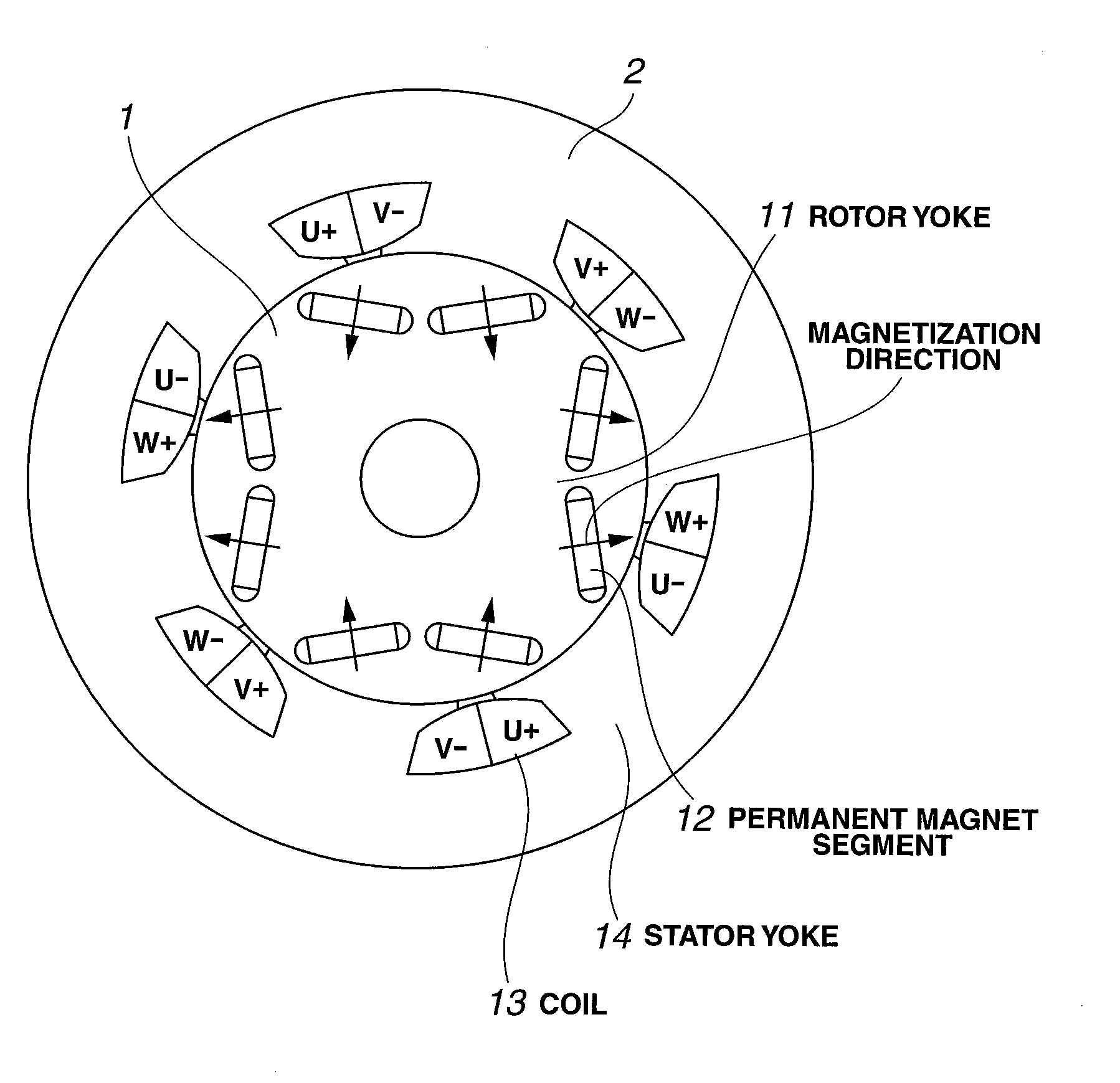
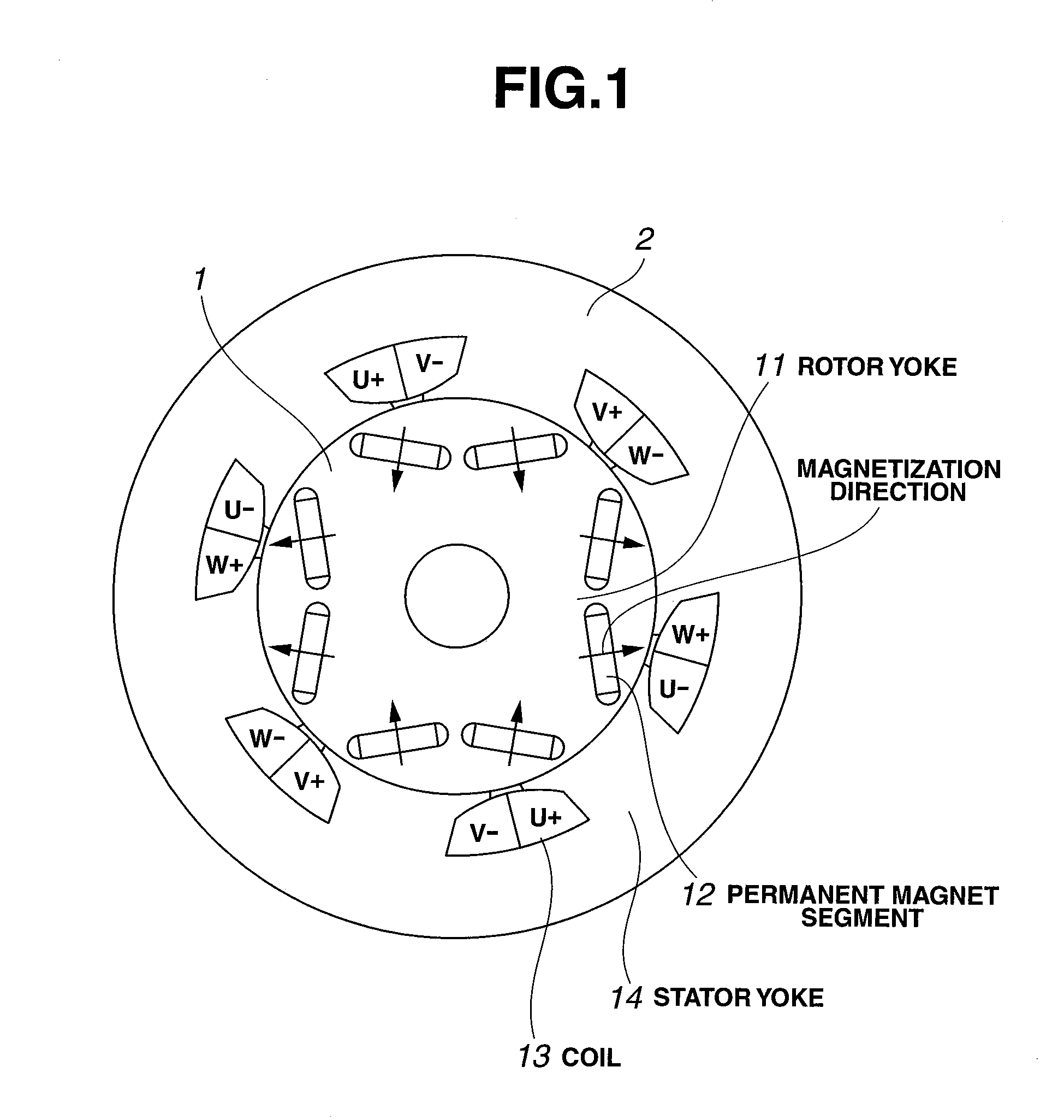
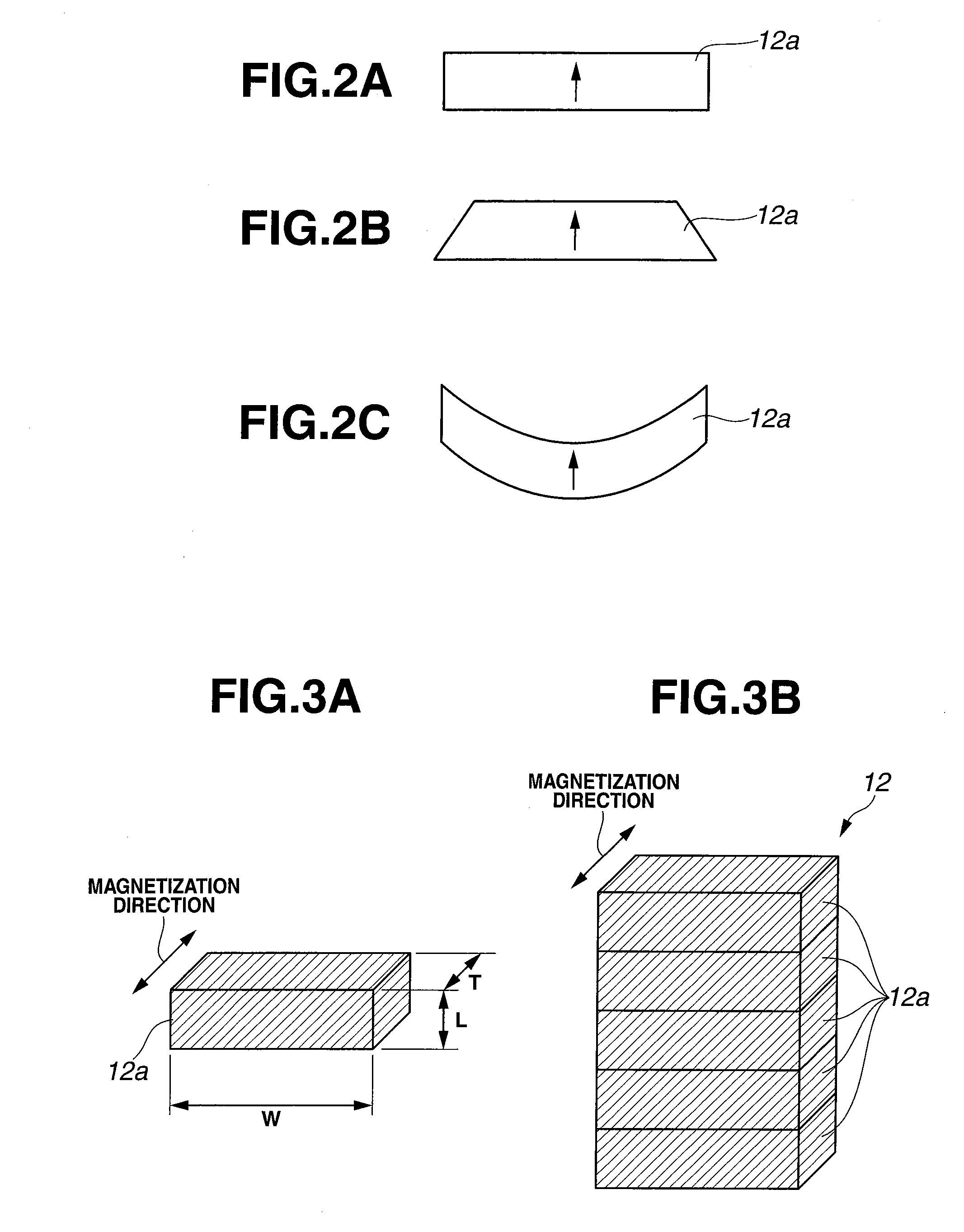
An interior permanent magnet (IPM) rotary machine comprises a rotor comprising a rotor yoke having bores and a plurality of permanent magnet segments disposed in the bores of the rotor yoke, each permanent magnet segment consisting of a plurality of magnet pieces. The rotor is assembled by inserting the plurality of unbound magnet pieces in each bore for stacking the magnet pieces, and fixedly securing the stacked magnet pieces in the bore.

Description

CROSS-REFERENCE TO RELATED APPLICATION[0001]This non-provisional application claims priority under 35U.S.C. §119(a) on Patent Application No. 2009-229612 filed in Japan on Oct. 1, 2009, the entire contents of which are hereby incorporated by reference.TECHNICAL FIELD[0002]This invention generally relates to a permanent magnet rotary machine comprising a rotor comprising a rotor yoke and a plurality of permanent magnet segments embedded in the rotor yoke and a stator comprising a stator yoke having a plurality of slots and windings therein, the rotor and the stator being disposed to define a gap therebetween, often referred to as interior permanent magnet (IPM) rotary machine. More particularly, it relates to a method for assembling the rotor. The rotor is used in a permanent magnet structure rotary machine best suited as electric vehicle motors, power generators, and factory automation (FA) motors capable of high speed rotation.BACKGROUND ART[0003]Sintered Nd-base magnets have a gro...

Claims


Application Information

Patent Timeline
Patent Type & Authority Applications(United States)
IPC IPC(8): H01F13/00C23C22/00C21D1/04H02K15/02
CPCH01F7/0221H02K15/03Y10T29/49012Y10T29/49009H02K1/2766
Inventor DOI, YUHITOMINOWA, TAKEHISANAKAMURA, HAJIMEHIROTA, KOICHI
Owner SHIN ETSU CHEM IND CO LTD
Why Eureka
Try Eureka