Line synchronized Electrical Device And Controlling Method Thereof

a technology of synchronized electrical devices and control devices, which is applied in the direction of process and machine control, ignition automatic control, instruments, etc., can solve the problems of increased wiring costs and complexity, insufficient brightness, and inability to add the extra wiring

Active Publication Date: 2011-04-07
GRAY RICHARD LANDRY
View PDF0 Cites 33 Cited by
  • Summary
  • Abstract
  • Description
  • Claims
  • Application Information

AI Technical Summary

Benefits of technology

[0010]The object of the present invention is to provide a line synchronized control method and a line synchronized control device generating a pulse width modulated (PWM) control signal in order to control an electrical apparatus. In particular the PWM control signal, with a frequency of multiples of a predetermined frequency (such as an AC power line frequency), is synchronized to an AC power line voltage. For instance, the present invention can be applied to dimming lights to ensure that the “

Problems solved by technology

There are several problems with using PWM dimming (or any form of dimming) for general purpose home or office lighting applications.
The first significant problem is how one controls the level of dimming for the lamp without requiring a separate control signal or separate control wiring.
There is nothing technically wrong with these methods of providing dimming for residential or commercial lighting; however the initial cost of adding the extra wiring or the cost of retrofitting an existing wiring system to include the extra control wiring would, in most cases, be prohibitive, as would using radio or IR controlled appliances.
The second major problem involves synchronizing the outputs of multiple lamps so that their brightnesses do not vary significantly enough to be noticed by the user.
If one runs separate control circuits to each lamp, so that each lamp may be pulsed on and off by the same signal, then one still has the same problem alluded to in the previous paragraph, i.e., increased wiring costs and complexity.

Method used


Image

  • Line synchronized Electrical Device And Controlling Method Thereof
  • Line synchronized Electrical Device And Controlling Method Thereof
  • Line synchronized Electrical Device And Controlling Method Thereof

Examples


embodiment 200

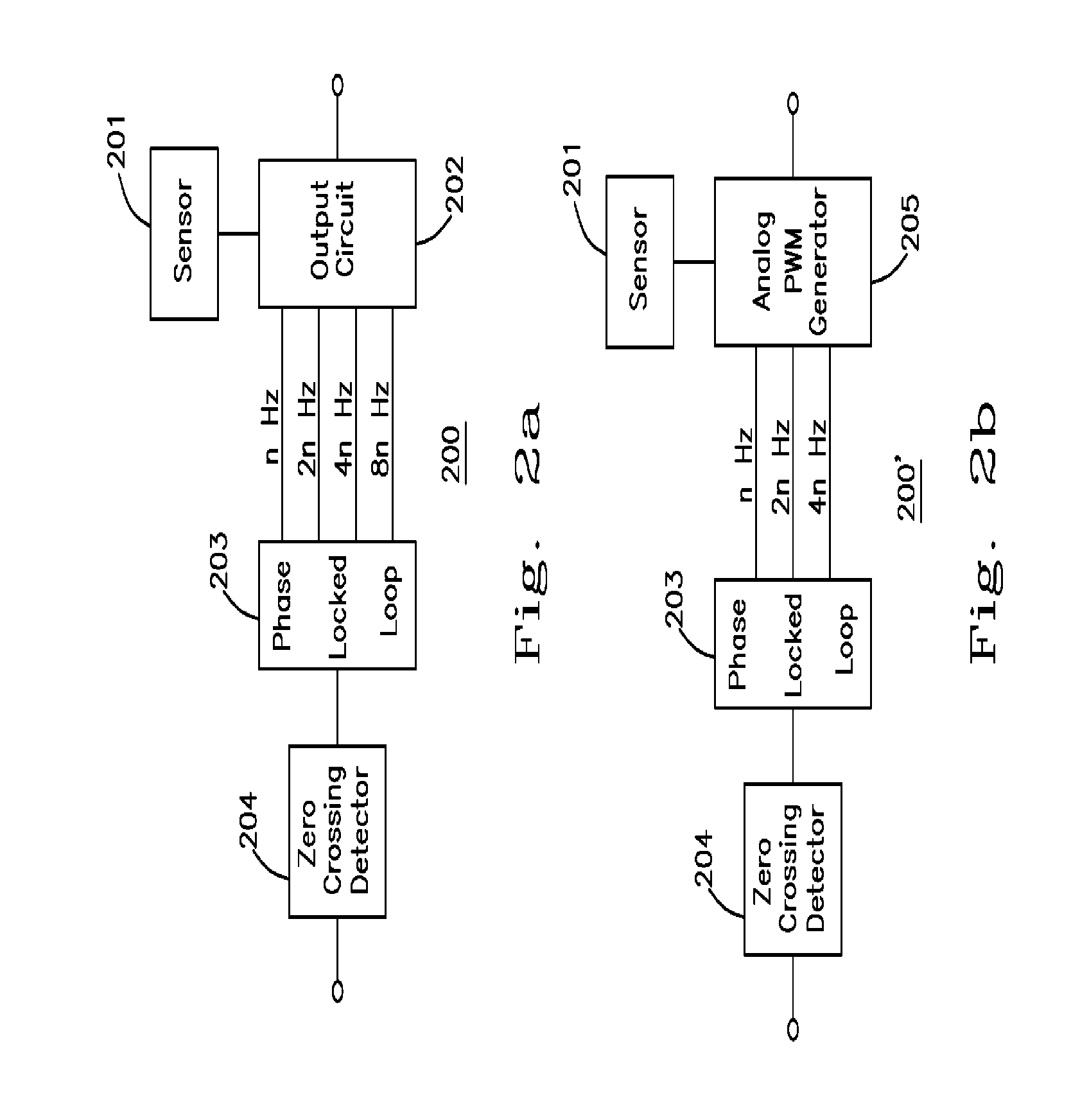
[0062]Please refer to FIG. 2a, which shows a second preferred embodiment of the present invention. The second preferred embodiment 200 includes a sensor 201 (most likely an ambient light sensor but in the most general case it could sense any physical property such as temperature, pressure, velocity etc.), an output circuit 202 coupled to the sensor 201, a PLL 203 coupled to the output circuit 202 and a zero crossing detector 204 coupled to the PLL 203. Particularly the sensor 201 outputs a signal to the output circuit 202 based on ambient light, temperature, pressure or other parameters in order to select a duty cycle for the PWM control signal of the output circuit 202. In this way the illumination in a room would stay constant even though another source of room light (such as sunlight) might be changing throughout the day.

[0063]Please refer to FIG. 2b which shows a modification of the second preferred embodiment of the present invention. The controlling device 200′ of FIG. 2b is s...

embodiment 300

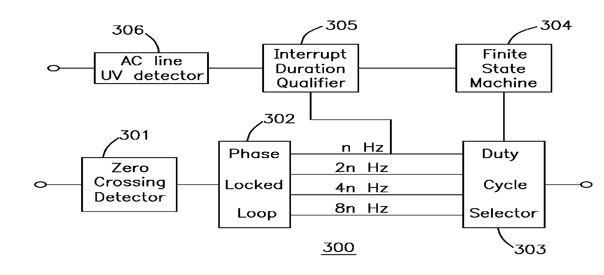
[0066]Please refer to FIG. 3, which shows a third preferred embodiment of the present invention. The third preferred embodiment 300 includes a zero crossing detector 301 coupled to a PLL 302; a duty cycle selector 303 coupled between the PLL 302 and a finite state machine 304; and an interrupt duration qualifier 305 coupled between the finite state machine 304 and an alternating current line under-voltage detector (AC Line UV Detector) 306. The zero crossing detector 301, the PLL 302 and the duty cycle selector 303 function as the aforementioned line synchronized control device.

[0067]The AC Line UV Detector 306 senses a voltage proportional to a DC rectified voltage. When that voltage is below a certain threshold, it signals that a line voltage interruption has occurred. The interrupt duration qualifier 305 determines if the interrupt duration is a valid interrupt or not. If the interrupt is too short, then it is ignored. If the interrupt is longer than some minimum, tmin, and short...

embodiment 500

[0076]Please refer to FIG. 6, which shows a second application of the present invention used in a lamp. In this application a rectifier circuit 610 is coupled to a control device 620 and a ballast 630, and the ballast 630 is coupled to at least one lamp 640 such as a CCFL or the other types of lamps described previously. The control device 620 functions as the fourth preferred embodiment 500 and comprises a shunt regulator 6201, a differential voltage detector 6202, a PLL 6203, a duty cycle selector 6204, a finite state machine 6205 and an interrupt duration qualifier 6206.

[0077]The rectifier circuit 610 has: a first 6101 and a second 6102 input terminal receiving an AC power line voltage such as a 60 HZ line voltage; a first output terminal 6103 coupled to the ballast 630 and providing a rectified direct current voltage; a second 6104 and a third 6105 output terminal coupled to the differential voltage detector 6202; a fourth output terminal 6106 coupled to the shunt regulator 6201...


PUM

PropertyMeasurementUnit
Fractionaaaaaaaaaa
Fractionaaaaaaaaaa
Fractionaaaaaaaaaa

Abstract

A controlling method for an electrical apparatus and a device thereof are provided in the present invention. The method includes the steps of: (a) providing an electrical apparatus and an AC power; (b) generating a control signal synchronized to the AC power; and (c) controlling the electrical apparatus by the control signal. The device includes a threshold detector, a phase-locked loop coupled to the threshold crossing detector and an output circuit coupled to the phase-locked loop.

Description

[0001]This application claims priority benefit under 35 USC 119 of PCT patent application, Ser. No PCT / US2009 / 044004, Filed May 14, 2009, and is published in English under PCT Article 21(2); which in turn claims priority of provisional patent application Ser. Nr. 61 / 130,607, filed Jun. 2, 2008.FIELD OF THE INVENTION[0002]The present invention relates to a controlling method and a control device. More particularly, it relates to a controlling method and a device to control an electrical apparatus by using a control signal synchronized with an AC power.BACKGROUND OF THE INVENTION[0003]The change from incandescent lighting to more efficient forms of electrical lighting has been, and will continue to be, the dominant trend in lighting. As the cost of electricity increases, the move to lighting solutions that provide more light output for less power (lumens per watt) becomes economically viable despite the higher initial costs of the more efficient lighting systems. Specifically, fluores...

Claims


Application Information

Patent Timeline
IPC IPC(8): H05B41/24H03L7/06G05B24/02
CPCH05B41/40H05B41/3927H05B47/185Y02B20/40
Inventor GRAY, RICHARD LANDRYTSAI, PO MING
Owner GRAY RICHARD LANDRY
Why Eureka
Try Eureka