
Method, device and use of a device for producing fuel from moist biomass

Active Publication Date: 2011-04-21
WERNER HANS
View PDF2 Cites 22 Cited by
  • Summary
  • Abstract
  • Description
  • Claims
  • Application Information

AI Technical Summary

Benefits of technology

[0013]This state, firstly, has the advantage that the biomass can be better further processed, for example it can be pumped (with or without adding additional liquid), and can be fed more easily to subsequent processing steps in the refinement process.
[0034]The value of the water separated during mechanical dehydration for the above purposes (as fertilizer, or as a starting material for the production thereof, or for fermentation to produce gas) can be further increased by using it as washing water, which is to say, so that it is enriched multiple times with biogenic material.

Problems solved by technology

Above all, however, the combustion-related harmful substances, which are present in the biomass and which, like chlorine, for example, accelerate the corrosion of the combustion systems or negatively influence the ash behavior of the combustion material, remain in the biomass when it is dried naturally by evaporation and reduce the value thereof as a fuel.
Above all, they require large amounts of energy, meaning that they negatively impact the energy balance of the fuel to be produced.
This is primarily due to the fact that compressing fresh biomass, such as grasses, which are commonly quite hard, requires considerable force and nonetheless results in insufficient moisture removal, so that the removal still leaves behind a significant moisture content in the material, which has already been compressed, thereby resulting in a particularly energy-consuming thermal drying process.
This also means that combustion-related harmful ingredients in the biomass are only removed to a limited extent, because these substances are largely water-soluble and thermal drying does not, therefore, reduce them.
In addition, the considerable forces required for compressing the biomass are associated with major wear on the equipment, which is all the more significant because the biomass frequently contains impurities in the form of matter that increases abrasion, such as sand, inorganic waste and the like, particularly when grass clippings from agricultural or public traffic areas are involved.

Method used


Image

  • Method, device and use of a device for producing fuel from moist biomass
  • Method, device and use of a device for producing fuel from moist biomass

Examples


Embodiment Construction

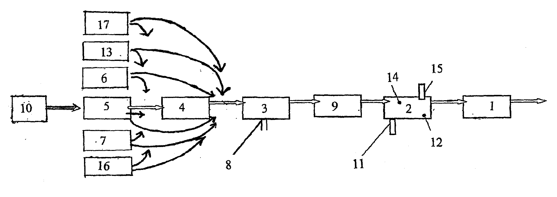
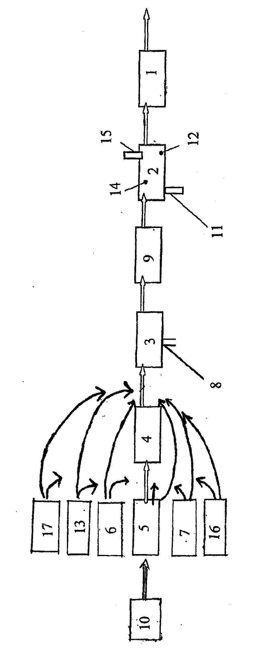
[0043]FIG. 1 shows a press-molding unit 1 for producing the fuel pellets, upstream of which a drying unit 2 for thermally drying the biomass to be pressed is connected.

[0044]The drying unit 2 comprises moisture meters 12 for properly adjusting the desired degree of dryness of the biomass to be pressed, and a temperature sensor 14 for optimally controlling the drying process. In addition, the drying unit 2 comprises a fluid line 11 for discharging moisture that develops and an exhaust gas line 15 for discharging gases that develop during drying.

[0045]A unit for mechanical dehumidification (pressing or the like) 3, by means of which as much moisture as possible is mechanically removed from the moist biomass by way of pressing, centrifuging or the like, is connected upstream of the drying unit 2, so as to increase the economy of the thermal drying process, which is considerably more energy-consuming.

[0046]The dehumidification unit 3—like the drying unit 2—comprises a fluid line 8, by m...


PUM

PropertyMeasurementUnit
Contentaaaaaaaaaa

Abstract

The invention relates to a method and to devices, and to the use of the same, for producing fuel pellets from moist biomass of all kinds, wherein the biomass is comminuted, mechanically dehydrated, dried, and then processed into pellets, wherein the comminution is a fine comminution and / or the biomass is washed before or after the comminution—optionally with the water developing during the mechanical dehydration—and is optionally pre-dehydrated and / or heated before the mechanical dehydration step, and is optionally comminuted again after the mechanical dehydration for easier drying.

Description

BACKGROUND OF THE INVENTION[0001]The present invention relates to a method, to a device, and to the use of such a device for producing press-molded fuel made of moist biomass of all types, such as agricultural, forestry and horticultural products, including waste. Examples include grass clippings, nursery or kitchen waste, and waste from the industrial processing of biomass, for example in food processing, paper manufacturing or the like.[0002]Such methods, and devices for carrying out the same, are known, for example, from WO 2004 / 067685 A1.[0003]These methods comprise, for example, a drying process prior to the final press-molding process that serves to produce the press-molded fuel, a pressing process prior to the drying process so as to reduce the moisture content, and a first comminution process prior to the pressing process, whereby the efficiency of the subsequent pressing operation, which is to say the resulting reduction of the water content of the moist biomass, is increas...

Claims


Application Information

Patent Timeline
IPC IPC(8): B02C19/00B08B7/04F26B7/00C05F7/00
CPCC10L5/363C10L5/44Y02E50/343Y02E50/10Y02E50/30C10L5/48
Inventor WERNER, HANS
Owner WERNER HANS
Learn More