Magnetic tunnel junction structure with perpendicular magnetization layers

a tunnel junction and perpendicular magnetization technology, applied in the field of magnetic tunnel junction structure with perpendicular magnetic anisotropy (pma) free layers, can solve the problems of increasing the power consumption of driving a device, difficult to fabricate a drive circuit for controlling a device, and large current required for reversing the magnetization direction, so as to reduce the critical current value, enhance the effect of thermal stability and high magneto-resistive ratio

Active Publication Date: 2011-04-21
KOREA INST OF SCI & TECH
View PDF4 Cites 13 Cited by
  • Summary
  • Abstract
  • Description
  • Claims
  • Application Information

AI Technical Summary

Benefits of technology

[0020]First, the magnetic tunnel junction structure can be configured so as to allow a magnetic coupling between the third magnetic layer having a large perpendicular magnetic anisotropic energy and the first magnetic layer adjacent to the non-magnetic layer (tunnel barrier), thereby maintaining the magnetization direction of the first magnetic layer to be perpendicular to the plane of the first magnetic layer upon current not being supplied, by virtue of the magnetic coupling between the first and third magnetic layers, resulting in reduction of a critical current value required for magnetization switching and enhancement of th

Problems solved by technology

Such a current-induced magneto-resistive device has a typical problem in that an amount of current required for reversing the magnetization direction is large.
If the current is large, then it is difficult to fabricate a drive circuit for controlling a device.
Such a problem may cause an increase of t

Method used


Image

  • Magnetic tunnel junction structure with perpendicular magnetization layers
  • Magnetic tunnel junction structure with perpendicular magnetization layers
  • Magnetic tunnel junction structure with perpendicular magnetization layers

Examples


Embodiment Construction

[0028]to Description will now be given in detail of various configurations of a magnetic tunnel junction structure in accordance with the present invention, with reference to the accompanying drawings.

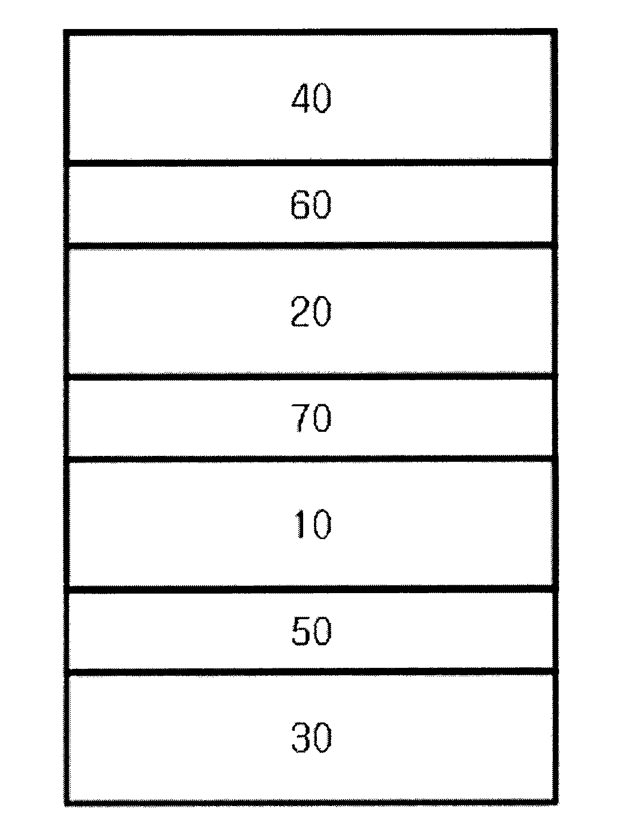
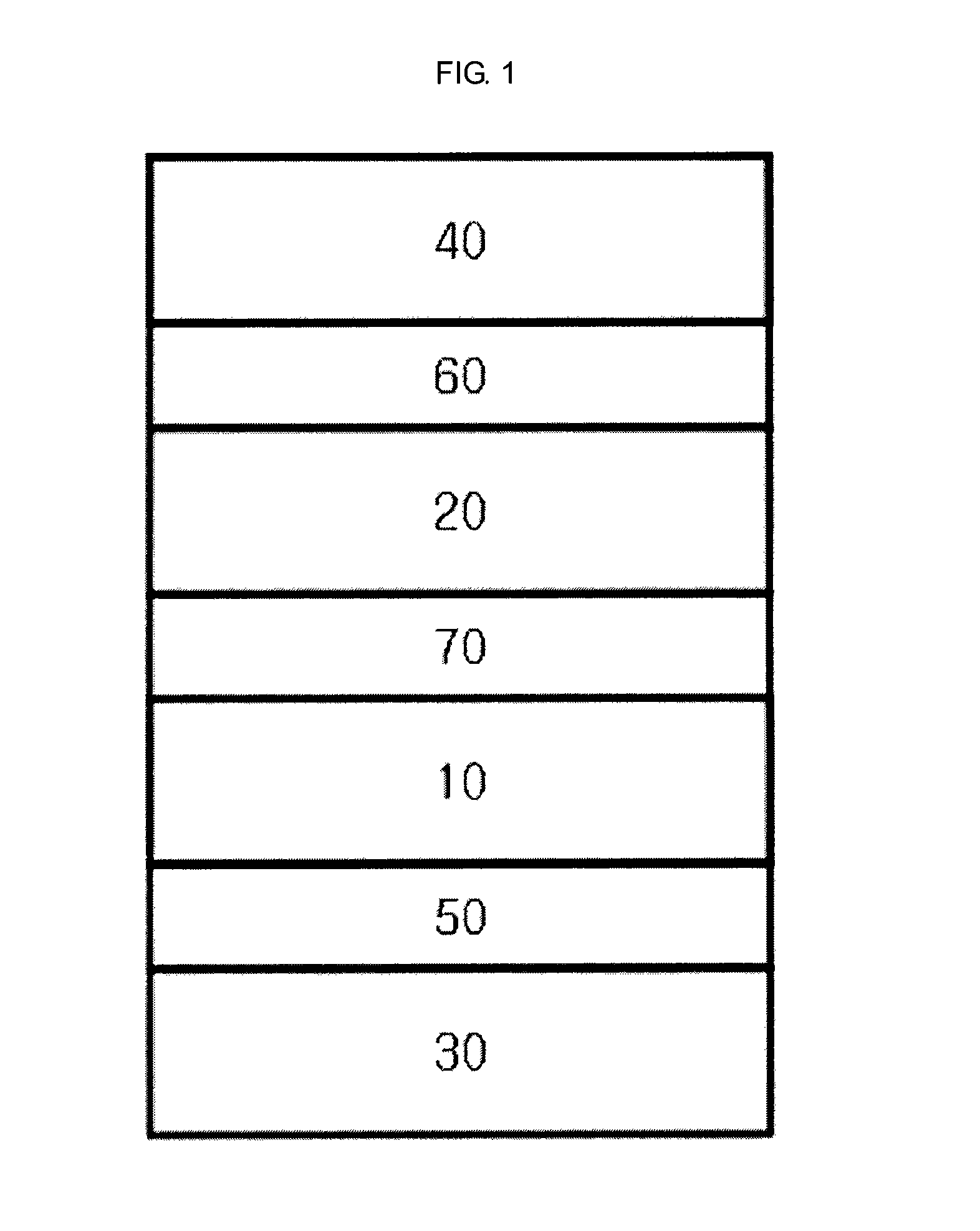
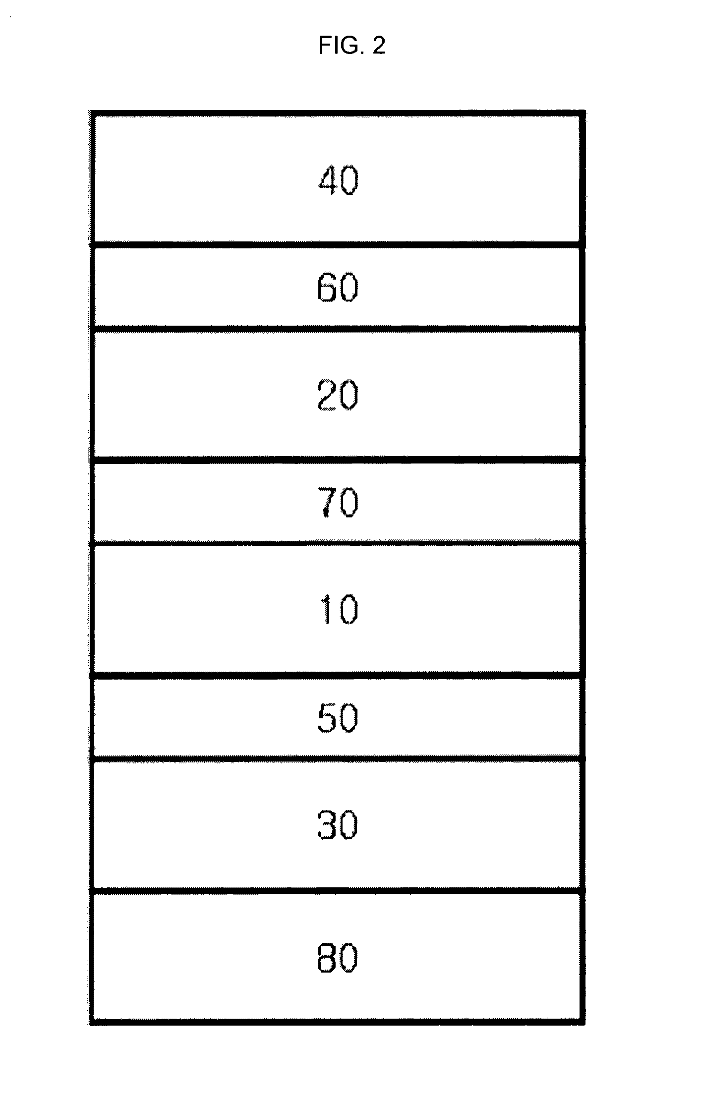
[0029]A magnetic tunnel junction structure according to the present invention may include a first magnetic layer having a fixed magnetization direction; a second magnetic layer having a reversible magnetization direction; a non-magnetic layer (tunnel barrier) formed between the first magnetic layer and the second magnetic layer; a third magnetic layer allowing the magnetization direction of the first magnetic layer to be aligned perpendicular with respect to a plane of the first magnetic layer by a magnetic coupling to the first magnetic layer, and having a perpendicular magnetic anisotropic energy thereof larger than an in-plane magnetic anisotropic energy thereof; a first crystal-structure separation layer formed between the first magnetic layer and the third magnetic layer for separ...


PUM


Abstract

Disclosed is a magnetic tunnel junction structure having perpendicular anisotropic free layers, and it could be accomplished to reduce a critical current value required for switching and maintain thermal stability even if a device is fabricated small in size, by maintaining the magnetization directions of the free magnetic layer and the fixed magnetic layer constituting the magnetic tunnel junction structure perpendicular to each other.

Description

CROSS-REFERENCE TO RELATED APPLICATION[0001]Pursuant to 35 U.S.C. §119(a), this application claims the benefit of earlier filing date and right of priority to Korean Application No. 10-2009-0099432, filed on Oct. 19, 2009, the contents of which is incorporated by reference herein in its entirety.BACKGROUND OF THE INVENTION[0002]1. Field of the Invention[0003]The present invention relates to a magnetic tunnel junction structure with perpendicular magnetic anisotropy (PMA) free layers.[0004]2. Background of the Invention[0005]Magnetic random access memories (MRAMs) currently developed for practical applications utilizes a magnetic tunnel junction (MTJ) element that forms a ferromagnetic tunnel junction as a magneto-resistive device. The MTJ device includes tri-layer consisting of two magnetic layers separated by a non-magnetic layer, and current flows by tunneling through the non-magnetic layer (tunnel barrier). As another structure of MTJ device, a so-called spin-valve structure is k...

Claims


Application Information

Patent Timeline
IPC IPC(8): H01L29/82
CPCB82Y10/00B82Y25/00G11B5/3906G11B5/3909H01F10/3286H01F10/3254H01F10/3268H01L43/08G11C11/16G11C11/161H10N50/10G11C11/15
Inventor MIN, BYOUNG CHULCHOI, GYUNG MINSHIN, KYUNG HO
Owner KOREA INST OF SCI & TECH
Why Eureka
Try Eureka