
Combined radiation therapy/pet apparatus

a combined radiation therapy and pet technology, applied in the field of combined radiation therapy/pet apparatus, can solve the problems of difficult positioning of tumors, change in tumor size, and inability to provide sufficient contrast between tumors and normal tissue, and achieve the effect of suppressing local sensitivity drops, reducing non-uniformity in sensitivity, and focusing on local sensitivity drops

Inactive Publication Date: 2011-04-21
NAT INST FOR QUANTUM & RADIOLOGICAL SCI & TECH
View PDF5 Cites 48 Cited by
  • Summary
  • Abstract
  • Description
  • Claims
  • Application Information

AI Technical Summary

Benefits of technology

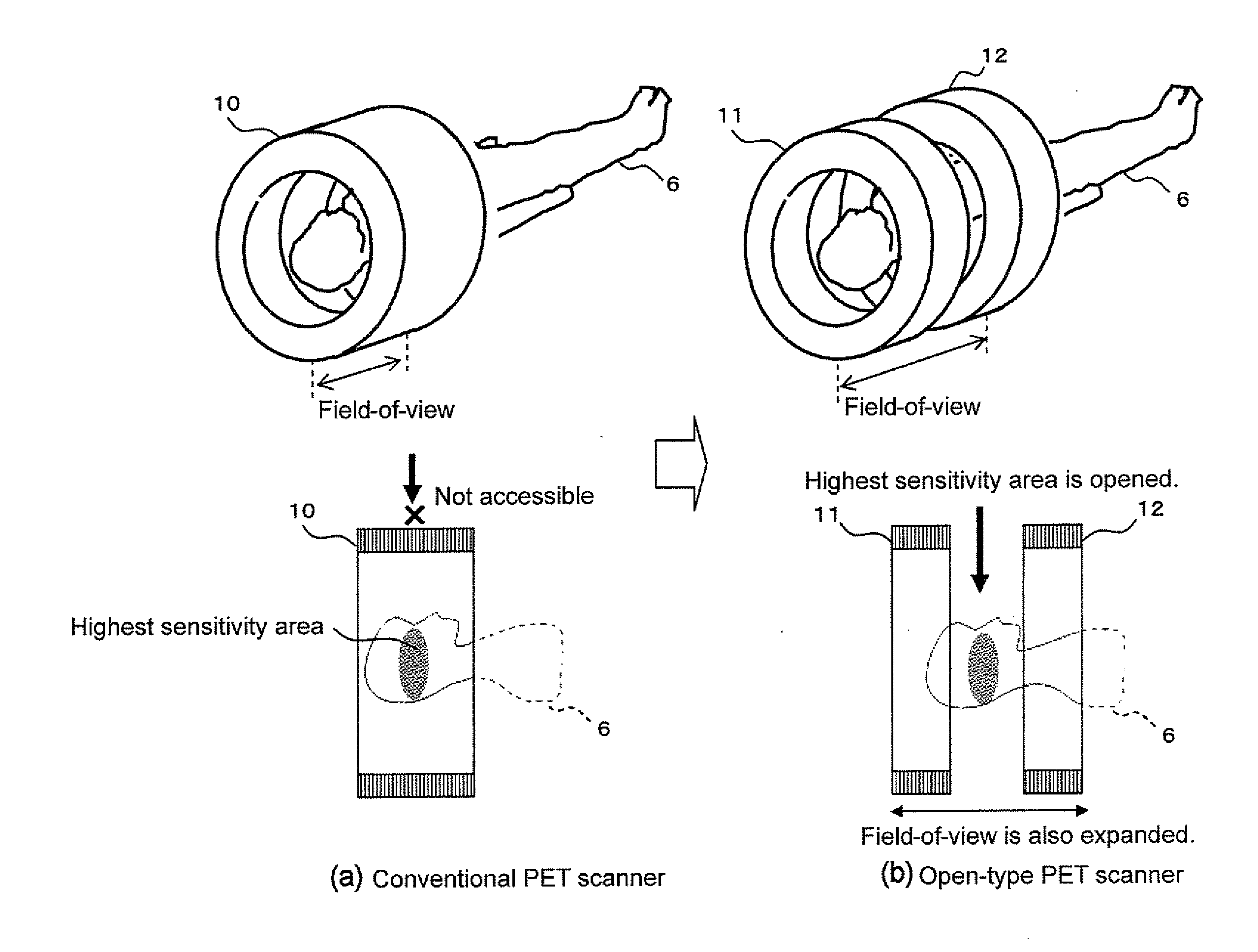
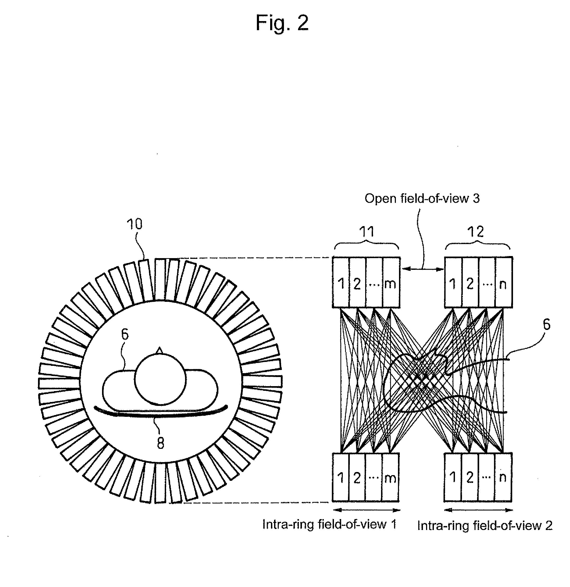
[0026]α a is a parameter for adjusting the balance between the effect of expanding the field-of-view in the direction of the body axis and the effect of reducing non-uniformity in sensitivity. α may be changed unit by unit or step by step within the range of 0<α≦1. Smaller α suppresses local sensitivity drops, but reduces the effect of expanding the field-of-view in the direction of the body axis. α fixed at the maximum value of 1, on the other hand, maximizes the field-of-view in the direction of the body axis, but with a higher emphasis on local sensitivity drops.

Problems solved by technology

In general, X-ray images fail to provide a sufficient contrast between tumor and normal tissue, and it is difficult to identify a tumor itself for positioning.
In addition to such misalignment of the irradiation field at the time of patient setup, other problems have been pointed out such as a change in the tumor size from the time of creation of the treatment plan, and respiratory and other movements of the tumor position.
Under the present circumstances, it is difficult to accurately identify whether irradiation is performed according to the treatment plan.
Even if the actual irradiation field deviates from the treatment plan, it is not easy to detect.
Such a PET device has had an essential problem that the detector gap causes a lack of information necessary for image reconstruction, resulting in nonuniform resolution and lower device sensitivity (P. Crespo et al., “On the detector arrangement for in-beam PET for hadron therapy monitoring,” Phys. Med. Biol., vol.
The long tunnel-shaped patient port, however, increases psychological stress on the patient 6 under examination as well as obstructs the patient's treatment.
However, there has been the problem that the increased number of detectors to constitute each multi-ring detector makes the device higher in price, larger in size, and more complicated in configuration.
In particular, when the open PET device is used to perform monitoring in particle radiotherapy, the beam irradiation may cause a performance drop or a failure of the detectors in cases such as when the detector circuit itself is affected.
Such an increase undesirably results in higher price, larger size, and further complication of the device.
This, however, has the problem that the patient's binding time increases as much as the moving time.
In addition, nuclides produced by the beam irradiation have an extremely short half-life of about several tens of seconds to 20 minutes, and the nuclides can even move within the living body due to the blood flow and other factors.

Method used


Image

  • Combined radiation therapy/pet apparatus
  • Combined radiation therapy/pet apparatus
  • Combined radiation therapy/pet apparatus

Examples


first embodiment

[0057]FIG. 6 shows the configuration of a Two identical ring-shaped detector rings 12a and 12b are arranged in parallel as independent gantries (60a, 60b), and a radiation irradiation device 24 is interposed between the detector rings 12a and 12b. This implements the treatment monitoring of observing the same area at the same time as treatment by PET. While the positions of the detector rings 12a and 12b may be fixed with respect to a bed 8 and the irradiation device 24, the detector rings here are configured to form a variable gap therebetween.

[0058]Specifically, the embodiment includes the detector rings 12a and 12b, gantry covers 60a and 60b which cover the respective detector rings, and the bed 8 on which a patient 6 lies. The gantries are each equipped with wheels 62, and have the function of moving back and forth on common or different rails 64.

[0059]To shift the open field-of-view in the direction of the body axis, the detector rings 12a and 12b are moved with respect to the...

third embodiment

[0072]FIG. 14 shows a third embodiment where the detectors are separated farther from the irradiation field in order to avoid a detector effect.

[0073]For chest treatment and the like, respiratory and other movements of the affected area need to be taken into account. Specifically, the treatment plan is created so as to administer irradiations in a relatively stable phase of breathing such as the expiratory state in the respiratory cycles. In treatment, respiration monitoring is performed to detect the motion of a marker or the like attached to the chest, and irradiation is administered only when the respiratory phase coincides with that on the treatment plan.

[0074]FIG. 15 shows the control of turning ON the irradiation depending on the expiratory phase of the respiratory signal. Here, PET measurement can be performed at the timing when the irradiation is OFF (inspiratory phase). This allows efficient PET measurement in the middle of a series of irradiations.

[0075]FIG. 15 is predicat...


PUM


Abstract

A combined radiation therapy / PET apparatus includes: an open PET device having multi-ring detector rings that are opposed to each other in the direction of the body axis so as to leave a gap therebetween; and a radiation therapy apparatus for performing radiation therapy through the gap. When imaging the condition of an affected area and a treatment beam for monitoring in radiation therapy of irradiating the affected area with X-rays, gamma rays, or particle beams, the apparatus covers a region of interest in the irradiation field of the radiation therapy with the field-of-view of the open PET device, thereby making possible the positioning of the irradiation field and treatment monitoring using PET images.

Description

TECHNICAL FIELD[0001]The present invention relates to a combined radiation therapy / PET apparatus which can image the condition of an affected area and a treatment beam for monitoring in radiation therapy of irradiating the affected area with X-rays, gamma rays, or particle beams.BACKGROUND ART[0002]Positron emission tomography (PET) is attracting attention as an effective test method for earlier diagnosis of cancer, cerebrovascular disease, dementia, etc. In PET, a compound labeled with a trace amount of positron emitting nuclides is administered and annihilation radiation emitted from inside the body is detected to create an image of biological functions such as sugar metabolism and check for a disease and its extent. PET devices for practicing PET have been put into actual use.[0003]The principle of PET will be described below. Positron emitted from a positron emitting nuclide by positron decay is annihilated with ambient electron to produce a pair of 511-keV annihilation radiatio...

Claims


Application Information

Patent Timeline
Patent Type & Authority Applications(United States)
IPC IPC(8): A61B6/00
CPCA61N5/1048A61N2005/1052A61B6/583G01T1/2985A61B6/037A61N2005/1087
Inventor YAMAYA, TAIGAMURAYAMA, HIDEOINANIWA, TAKU
Owner NAT INST FOR QUANTUM & RADIOLOGICAL SCI & TECH
Learn More