High efficiency module
a module and high-efficiency technology, applied in the field of modules, can solve the problems of reducing the switching performance increasing the power consumption of the dc-dc converter, and electromagnetic interference (emi), and achieve the effect of reducing the wiring resistance and reducing the wiring inductan
- Summary
- Abstract
- Description
- Claims
- Application Information
AI Technical Summary
Benefits of technology
Problems solved by technology
Method used
Image
Examples
first embodiment
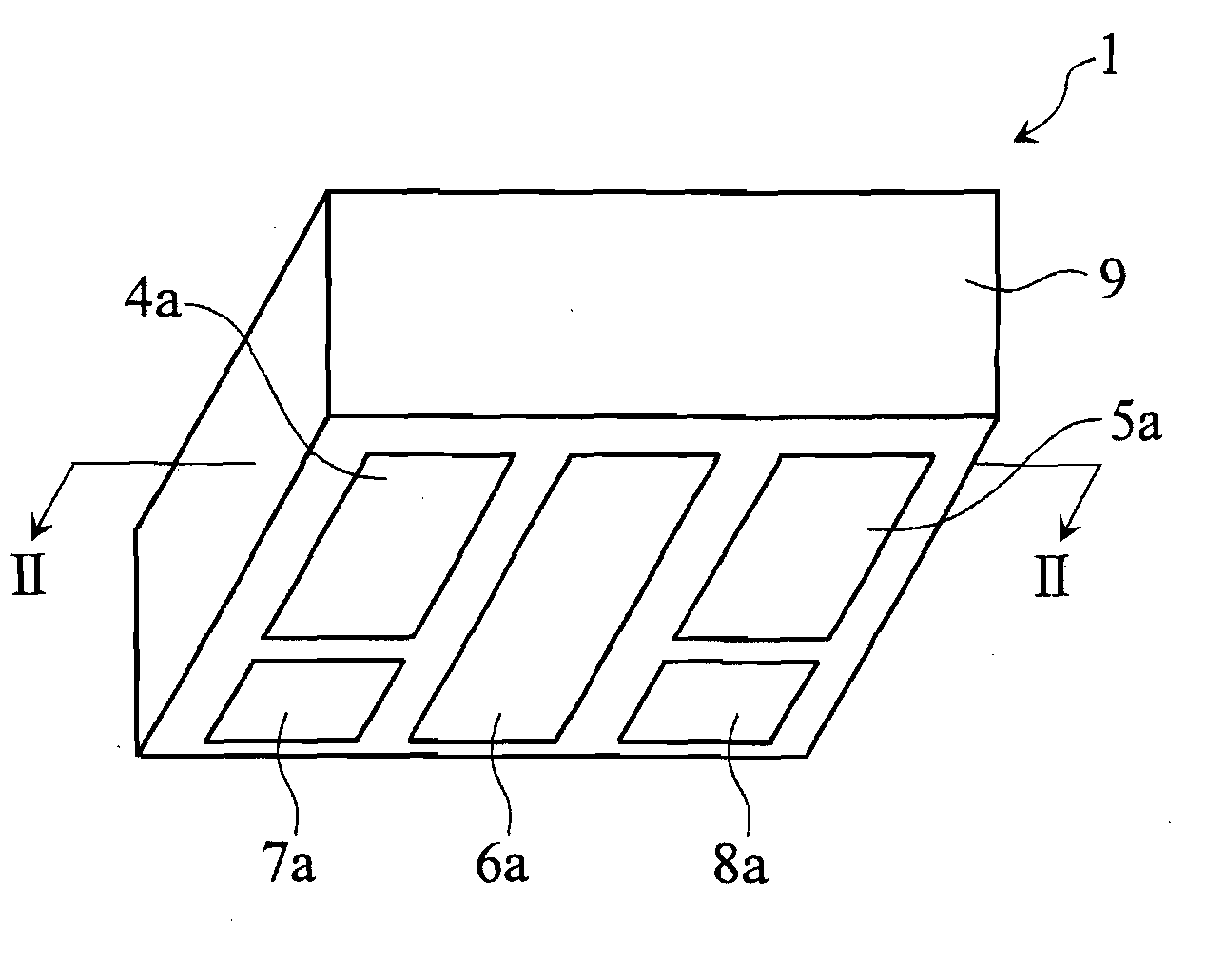
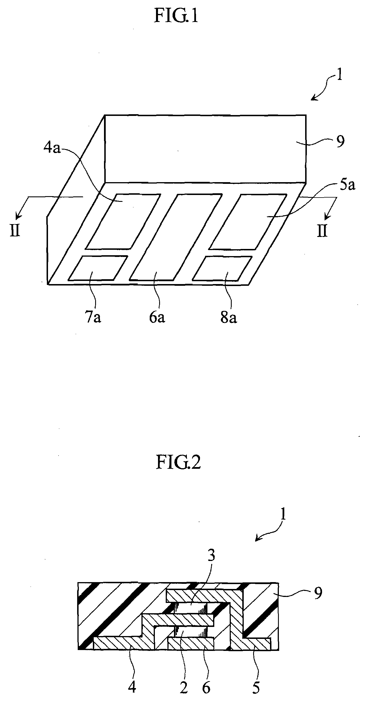
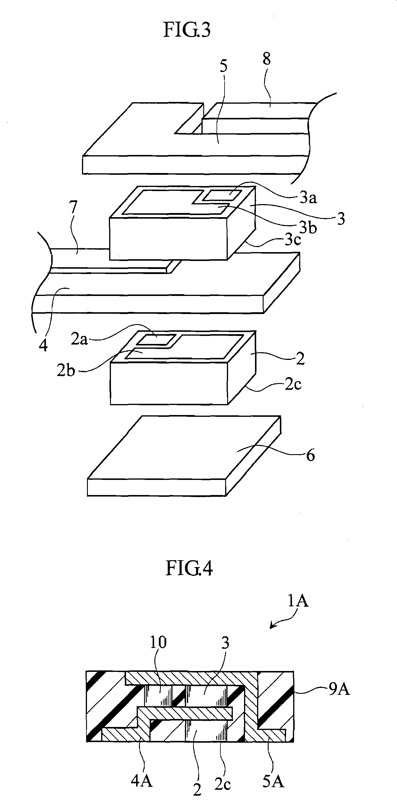
[0034]Embodiments of the present invention will be described below with reference to the accompanying drawings. FIGS. 1 to 3 illustrate a module according to the present invention. The module of this embodiment corresponds to a single device into which the high-side MOSFET 110 and the low-side MOSFET 120 shown in FIG. 13 are integrated.
[0035]The illustrated module 1 includes a high-side MOSFET chip 2, a low-side MOSFET chip 3, conductive lead frames 4-8, and a resin package 9.
[0036]As shown in FIG. 3, the upper surface of the high-side MOSFET chip 2 is provided with a gate electrode 2a and a source electrode 2b, and the lower surface of the chip is provided with a drain electrode 2. As known, a bipolar transistor has three electrodes called a base electrode, an emitter electrode, and a collector electrode. These electrodes correspond to the gate electrode, the source electrode, and the drain electrode of a MOSFET, respectively.
[0037]The gate electrode 2a of the high-side MOSFET chip...
fourth embodiment
[0063]By using the module 1C of the fourth embodiment for the MOSFET 21 and the diode 22 of the step down DC-DC converter 20 shown in FIG. 11 (indicated by dotted lines in FIG. 11), the wiring resistance and inductance between the source electrode of the MOSFET 21 and the cathode electrode of the diode 22 can be reduced. This enables reduction in power consumption and improvement in performance of the step down DC-DC converter 20.
[0064]A module according to the fifth embodiment of the present invention differs from the module 1 of the first embodiment (see FIG. 2) in that an NPN transistor and a PNP transistor are employed in place of the high-side MOSFET chip 2 and the low-side MOSFET chip 3, respectively. Drawings to illustrate the fifth embodiment are omitted since they would be the same as FIGS. 1-3.
[0065]FIG. 12 is a circuit diagram of a drive circuit. A drive circuit 30 includes an NPN transistor 31, a PNP transistor 32, capacitors 33, 34, a gate resistance 35, a resistance 36...
fifth embodiment
[0067]By using the module of the fifth embodiment for the NPN transistor 31 and the PNP transistor 32 of the drive circuit 30 shown in FIG. 12 (indicated by bold dotted lines in FIG. 12), the wiring resistance and inductance between the emitter electrode of the NPN transistor 31 and the emitter electrode of the PNP transistor 32 can be reduced. This enables reduction in power consumption and improvement in performance of the drive circuit 30.
PUM
 Abstract
Description
Claims
Application Information
 - R&D
- Intellectual Property
- Life Sciences
- Materials
- Tech Scout
- Unparalleled Data Quality
- Higher Quality Content
- 60% Fewer Hallucinations
Browse by: Latest US Patents, China's latest patents, Technical Efficacy Thesaurus, Application Domain, Technology Topic, Popular Technical Reports.
© 2025 PatSnap. All rights reserved.Legal|Privacy policy|Modern Slavery Act Transparency Statement|Sitemap|About US| Contact US: help@patsnap.com


