
Generation of Chemical Reagents for Various Process Functions Utilizing an Agitated Liquid and Electrically Conductive Environment and an Electro Chemical Cell

a technology of electrochemical cells and reagents, applied in the field of process streams, can solve the problems that water from pressure washing operations is no longer permitted to be disposed of on the land or down storm sewers, and achieve the effect of reducing the amount of water

Active Publication Date: 2011-05-05
ROBERT BOSCH GMBH
View PDF11 Cites 4 Cited by
  • Summary
  • Abstract
  • Description
  • Claims
  • Application Information

AI Technical Summary

Benefits of technology

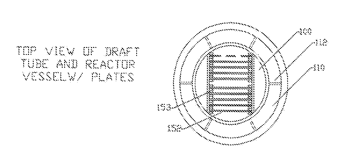
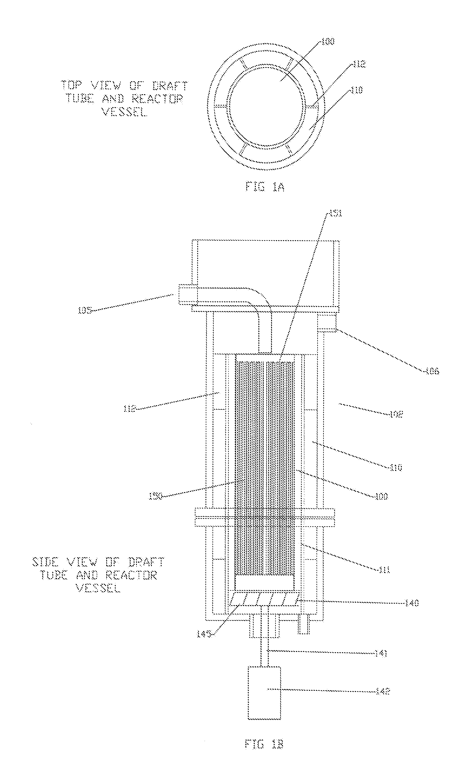
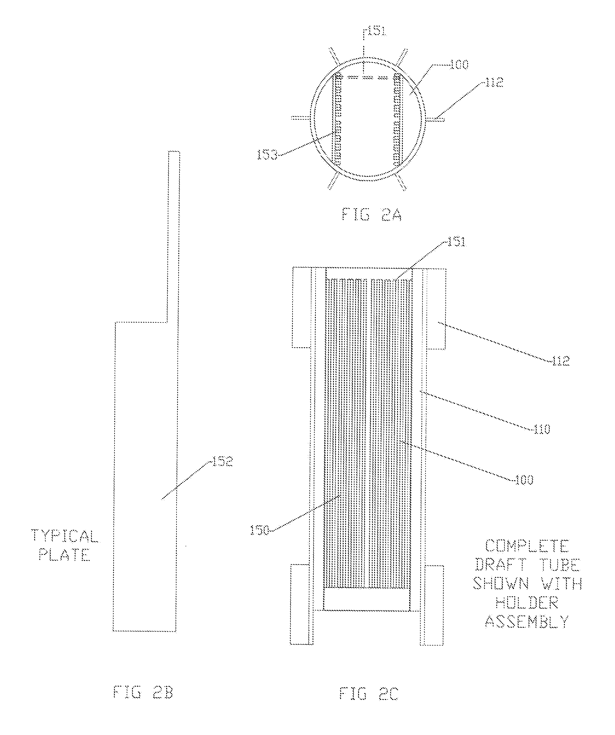
[0022]The limitations of the electro-coagulation process and apparatus are removed or diminished by the method and apparatus of the present disclosure. In contrast to the detailed fabrication requirements and tolerances of the prior art electrolytic cell, the present disclosure provides for simplified fabrication of the reactor vessel and plates as well as ease of insertion / removal and maintenance of the plates while in service. Fabrication is simplified and requiring less rigid tolerance due to the decreased surface area requirements of the smaller plates and extended dwell time within the vessel. In regard to the high scaling potentials, much of the electrochemical reaction occurs away from the plates, therefore there is less opportunity for the particles to foul or scale on the plate surface. High heat generation does not occur in view of the smaller surface area of the plates, diminished electrical power requirements, and high liquid flow rate over the plate surface. Also the agitated liquid disperses the heat throughout the vessel.
[0023]The electro-coagulation process utilizes electrically conductive plates with large surface areas and which require large electrical loading. This loading can be approximately 25-125 amps per gallon treated (dependent on stream conditions). This disclosure allows for multiple circulation of a waste stream across the energized plates. This recirculation creates repeat opportunities for the desired electrochemical reaction to occur. The flow of the waste stream also causes the chemical reactions to occur away from the plates. This minimizes scaling on the plate surfaces.
[0036]In this embodiment, floc formation does not occur exclusively at the plate surface of the electrochemical cell. In this embodiment, the electrical cell is utilized as a generator of physiochemical forces and reagents (metallic and hydroxide ions) and the process fluid is provided in a well mixed environment. The well mixed environment allows for rapid distribution of all chemical reagents uniformly in the process fluid. In this manner, the utilization of the reagents is more efficient. A secondary zone downstream of the reaction device is required to allow precipitant formation and finalization of the chemical reactions. In this embodiment, the potential for scale or fouling formations on the electrochemical cell is greatly reduced. Periodic reversal in the cell polarity is desired to ensure that the cell plates maintain even wear though their useful life.
[0037]It is also presented that the volume of the process fluid contained in the vessel is of significant volume to generate a defined residence time for contact with the electrical field of the electrochemical cell. The required contact time (defined as residence time) can vary on implementation (flow and size) and the requirements of the process. The residence time is the quantity of time the solution is circulating within the vessel. The residence time can vary from a few seconds of contact time to multiple hours. In one embodiment, the residence (dwell) time of liquid in the vessel can be controlled by the quantity of liquid entering the vessel. Less quantity entering results in less quantity exiting the vessel. The residence time can be controlled. In one embodiment, the flow rate within the vessel can also be controlled by controlling the speed of the agitator.
[0038]The physical design of this disclosure allows for the process fluids in the reactor (the process vessel) to be in contact with the electrical field (the total surface area of the electrical plates) of the electrochemical cell multiple times during the residence time in the reaction chamber. The process fluids contained in the reaction device are circulated at varying rates (depending on agitation speed) and are subjected to the forces generated by the electrical cell multiple times while in the reagent reactor. The residence time and electrical cell contact equivalent are easily calculated based on reaction chamber volume, feed rate and circulation rate within the chamber. In this configuration, electrical cells of much smaller surface area are utilized (as compared to conventional electro coagulation configurations) due to the multiple passes over the cells while in the reaction chamber. This provides for significantly reduced total electrical cell surface area as an effective surface area is created due to the multiple contacts in circulation. This is in contrast to the previously used electro-coagulation apparatus with the liquid typically making a single pass over of the electrical plates. Lower amperage is required for the reaction vessel subject of this invention. The configuration of this disclosure also eliminates / reduces the formation of particles on the plates (thereby reducing the potential of scale formation on the plate surface—scale formed on the plates produces an insulator from the process fluid and reduces the efficiency of the electrical cell). It also provides for a more compact treatment mechanism than possible with the prior art versions.

Problems solved by technology

The source of this liquid, e.g., process water, can vary and may contain a vast array of contaminates.
In one example, water from pressure washing operations is no longer permitted to be disposed onto the land or down storm sewers.

Method used


Image

  • Generation of Chemical Reagents for Various Process Functions Utilizing an Agitated Liquid and Electrically Conductive Environment and an Electro Chemical Cell
  • Generation of Chemical Reagents for Various Process Functions Utilizing an Agitated Liquid and Electrically Conductive Environment and an Electro Chemical Cell
  • Generation of Chemical Reagents for Various Process Functions Utilizing an Agitated Liquid and Electrically Conductive Environment and an Electro Chemical Cell

Examples


Embodiment Construction

[0021]It is the intention of this disclosure to describe a method and apparatus that can be configured in various embodiments and that will have a broad range of applications. These can range from potable water, municipal waste waters, industrial process waters, industrial waste water, cleaning solutions, chemical reaction processes or by-products (industrial and medical), electrical production, hydrogen production, as well as other applications.

[0022]The limitations of the electro-coagulation process and apparatus are removed or diminished by the method and apparatus of the present disclosure. In contrast to the detailed fabrication requirements and tolerances of the prior art electrolytic cell, the present disclosure provides for simplified fabrication of the reactor vessel and plates as well as ease of insertion / removal and maintenance of the plates while in service. Fabrication is simplified and requiring less rigid tolerance due to the decreased surface area requirements of the...


PUM

PropertyMeasurementUnit
Timeaaaaaaaaaa
Electrical conductivityaaaaaaaaaa
Widthaaaaaaaaaa

Abstract

The disclosure teaches an apparatus for circulating electrically conductive solutions between electro-chemical cells. The apparatus is able to decrease the size or surface area of the cells and operate the electro-chemical at reduced amperage. Movement of the solution over the plates also facilitates reduced build up of scale on the plates. The flow rate or treatment dwell time can be controlled.

Description

RELATED APPLICATION[0001]This application claims priority to and incorporates by reference herein provisional application Ser. No. 61 / 257,334 entitled “Generation of Chemical Reagents for Various Process Functions Utilizing an Agitated Liquid and Electrically Conductive Environment and an Electro Chemical Cell” filed Nov. 2, 2009.BACKGROUND TO DISCLOSURE[0002]Many process streams exist that require advanced chemical treatment. These streams range from potable drinking water to industrial process streams. These industrial process streams contain a multitude of soluble compounds that require treatment by some process. This can include pretreatment before discharge into a publically owned treatment works (POTW). The soluble compounds include but are not limited to arsenic, nitrates, organics, compounds in potable water as well as a list of a multitude of compounds dissolved in industrial process waters. These contaminants and the variety of contaminants make the process streams difficu...

Claims


Application Information

Patent Timeline
IPC IPC(8): C02F1/463C02F1/52C25B9/00C25B9/18
CPCC02F1/463C02F2201/46145C02F2201/4619C02F2201/4617C02F2201/4615
Inventor PROKOP, DAN
Owner ROBERT BOSCH GMBH
Learn More