Whole Slide Fluorescence Scanner

a fluorescence scanner and slide technology, applied in the field of digital pathology, can solve the problems of low efficiency of light emission, and low efficiency of line scan cameras in brightfield scanning, and achieve the effects of improving sensitivity, speed and accuracy, and increasing line ra

Active Publication Date: 2011-05-19
LEICA BIOSYST IMAGING
View PDF12 Cites 89 Cited by
  • Summary
  • Abstract
  • Description
  • Claims
  • Application Information

AI Technical Summary

Benefits of technology

[0008]Accordingly, to provide the speed and accuracy advantages of a line scan camera system in fluorescence scanning, a fluorescence digital pathology system is provided that uses a monochrome time delay integration (“TDI”) line scan camera having multiple linear arrays (“TDI line scan camera”). The monochrome TDI line scan camera enables higher line rates for scanning fluorescence samples by using multiple linear arrays that provide increased sensitivity compared to a single array line scan camera. This is particularly useful in fluorescence scanning where the signal is typically much weaker than in brightfield microscopy. The system also uses oblique brightfield illumination for fast and accurate tissue finding and employs a unique double sweep focus scoring and objective lens height averaging technique to identify focus points and create a focus map that can be followed during subsequent scanning to provide autofocusing capability.
[0009]The system additionally uses the histogram of a small scanned area of the sample to determine the optimal line rate for the TDI line scan camera during scanning and thereby provides optimal exposure time for scanning the fluorescence sample. The system also employs an efficient scanning workflow to scan the multiple channels of a fluorescence sample. With respect to stripe alignment, the system uses contrast in the overlap region between adjacent stripes to align adjacent stripes when sufficient contrast is available and also aligns adjacent stripes for each channel in a multi-channel sample. Moreover, the digital pathology system has an illumination system that optionally employs beam shaping to illuminate an oval or rectangular area that is in close registration with the rectangular sensor of the TDI line scan camera, which preserves the fluorescence sample and also allows for shorter exposure times. The system also provides data management capabilities to address the challenges associated with scans of multi-channel samples. The system similarly provides visualization and analysis capabilities to address single and multi-channel viewing and analysis of the digital slide image.

Problems solved by technology

The significant advantages of line scan cameras in brightfield scanning have yet to be successfully adopted with fluorescence scanners because the inherent differences between fluorescence and brightfield samples requires new techniques for automated scan and display of fluorescence samples.
As the efficiency of this photoluminescence phenomenon is very low, the amount of emitted light is also very low.
Additionally, the task of finding the tissue of fluorescence samples is extremely challenging because the samples are typically transparent in brightfield illumination, which is the most efficient illumination mode in which to do tissue finding.
Even more challenging with fluorescence scanning using a line scan camera is the task of automatic focus plane recognition.
Another significant challenge with fluorescence scanning is determining the optimal exposure time for fluorescent samples because they vary significantly in emission intensity.
Other very significant challenges related to fluorescence scanning using a line scan camera include the scanning workflow required for tissue finding, autofocus, autoexposure, multi-channel scanning (scanning samples having multiple fluorochromes with different emission wavelengths), stripe alignment, and illumination (e.g., epi-illumination).
Additionally, with respect to multi-channel images, new and significant challenges are present for data management, visualization, and analysis related to the resulting image data.

Method used


Image

  • Whole Slide Fluorescence Scanner
  • Whole Slide Fluorescence Scanner
  • Whole Slide Fluorescence Scanner

Examples


Embodiment Construction

[0020]Embodiments disclosed herein provide for a whole slide fluorescence scanning system and methods of operation of a fluorescence scanning system. After reading this description it will become apparent to one skilled in the art how to implement the invention in various alternative embodiments and alternative applications. However, although various embodiments of the present invention will be described herein, it is understood that these embodiments are presented by way of example only, and not limitation. As such, this detailed description of various alternative embodiments should not be construed to limit the scope or breadth of the present invention as set forth in the appended claims.

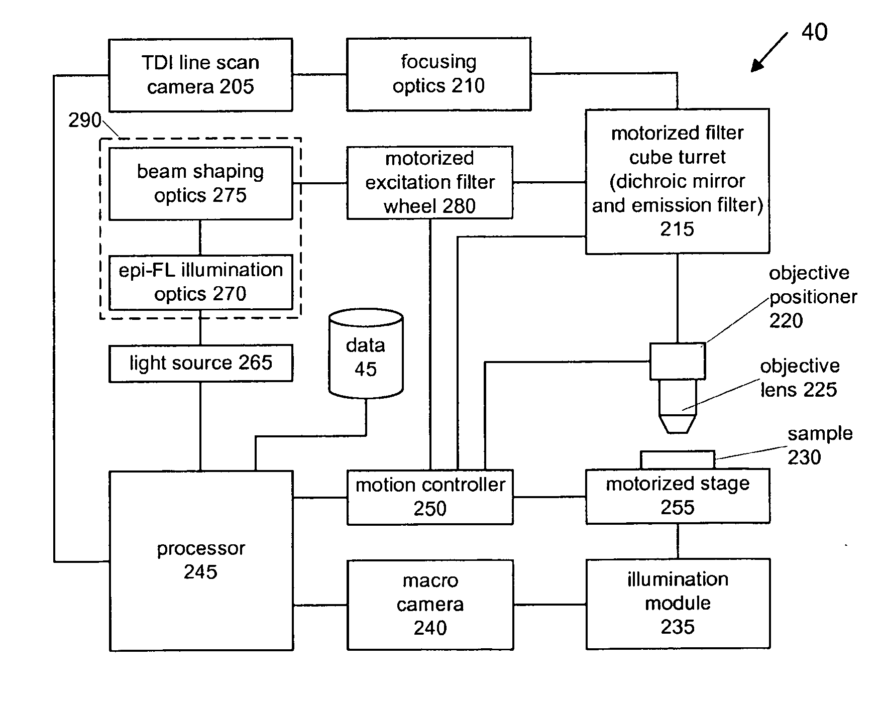
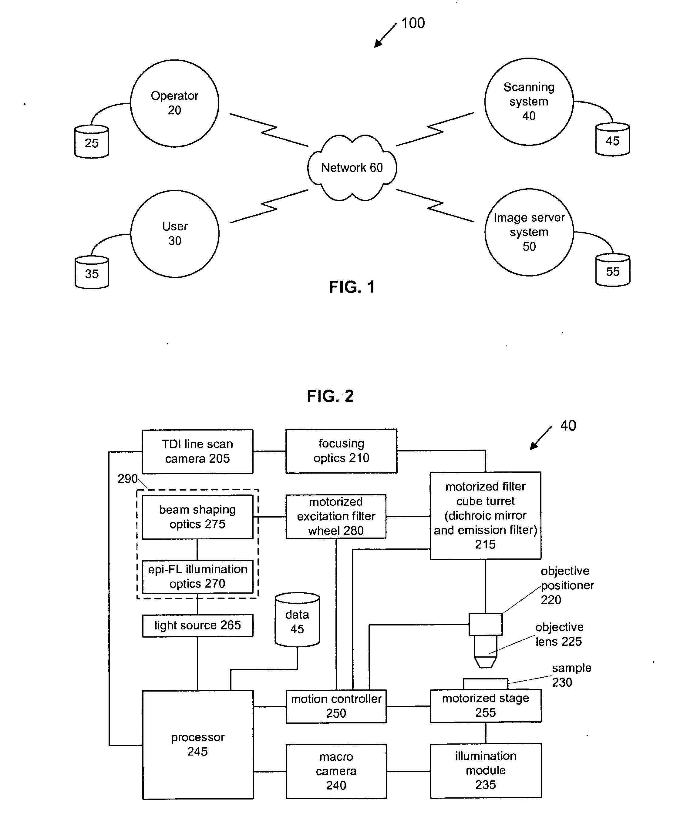
[0021]FIG. 1 is a network diagram illustrating an example fluorescence scanner system 100 according to an embodiment of the invention. In the illustrated embodiment, the system 100 comprises a fluorescence scanning system 40 that is configured with a data storage area 45. The fluorescence scanning...


PUM


Abstract

A whole slide fluorescence digital pathology system is provided that uses a monochrome TDI line scan camera, which is particularly useful in fluorescence scanning where the signal is typically much weaker than in brightfield microscopy. The system uses oblique brightfield illumination for fast and accurate tissue finding and employs a unique double sweep focus scoring and objective lens height averaging technique to identify focus points and create a focus map that can be followed during subsequent scanning to provide autofocusing capability. The system also scans and analyzes image data to determine the optimal line rate for the TDI line scan camera to use during subsequent scanning of the digital slide image and it also creates a light profile to compensate for loss of illumination light due to roll off.

Description

BACKGROUND[0001]1. Field of the Invention[0002]The present invention is generally related to digital pathology using line scan cameras and more particularly related to scanning fluorescent microscope samples using a line scan camera.[0003]1. Related Art[0004]Brightfield scanners rely on the use of sensitive color cameras such as line scan cameras or area scan cameras. Line scan cameras, which are superior to area scan cameras for digital pathology, require precise movement of the slide (and the stage upon which the slide rests) in synchronization with the data capture parameters of the camera.[0005]The significant advantages of line scan cameras in brightfield scanning have yet to be successfully adopted with fluorescence scanners because the inherent differences between fluorescence and brightfield samples requires new techniques for automated scan and display of fluorescence samples. One fundamental difference between brightfield and fluorescence scanning is that fluorescence scan...

Claims


Application Information

Patent Timeline
Patent Type & Authority Applications(United States)
IPC IPC(8): H04N7/18
CPCG01N21/6458G02B21/002G02B21/16G06T7/0024G06T2207/10056G06T2207/10064H04N5/3692G01N21/64G02B21/00G01N2021/6471G02B21/0076G02B21/0084G06T2207/30024G06T7/30G02B21/367G06V20/693H04N25/701
Inventor NAJMABADI, PEYMANCRANDALL, GREGORY J.STEARRETT, AARON ALANSOENKSEN, DIRK G.LEE, CHRISTOPHER ADAMPERZ, CYNTHIA
Owner LEICA BIOSYST IMAGING
Why Eureka
Try Eureka