
Device and Method For Particle Separation

a technology of gas specie and aerosolized gas, which is applied in the direction of dispersed particle separation, separation process, centrifuge, etc., can solve the problems of inability to achieve acceptable production, inability to achieve centrifuge, and small centrifuge size, etc., to achieve enhanced separation effect and increase centrifugal pressur

Inactive Publication Date: 2011-05-26
TENOROC
View PDF9 Cites 6 Cited by
  • Summary
  • Abstract
  • Description
  • Claims
  • Application Information

AI Technical Summary

Benefits of technology

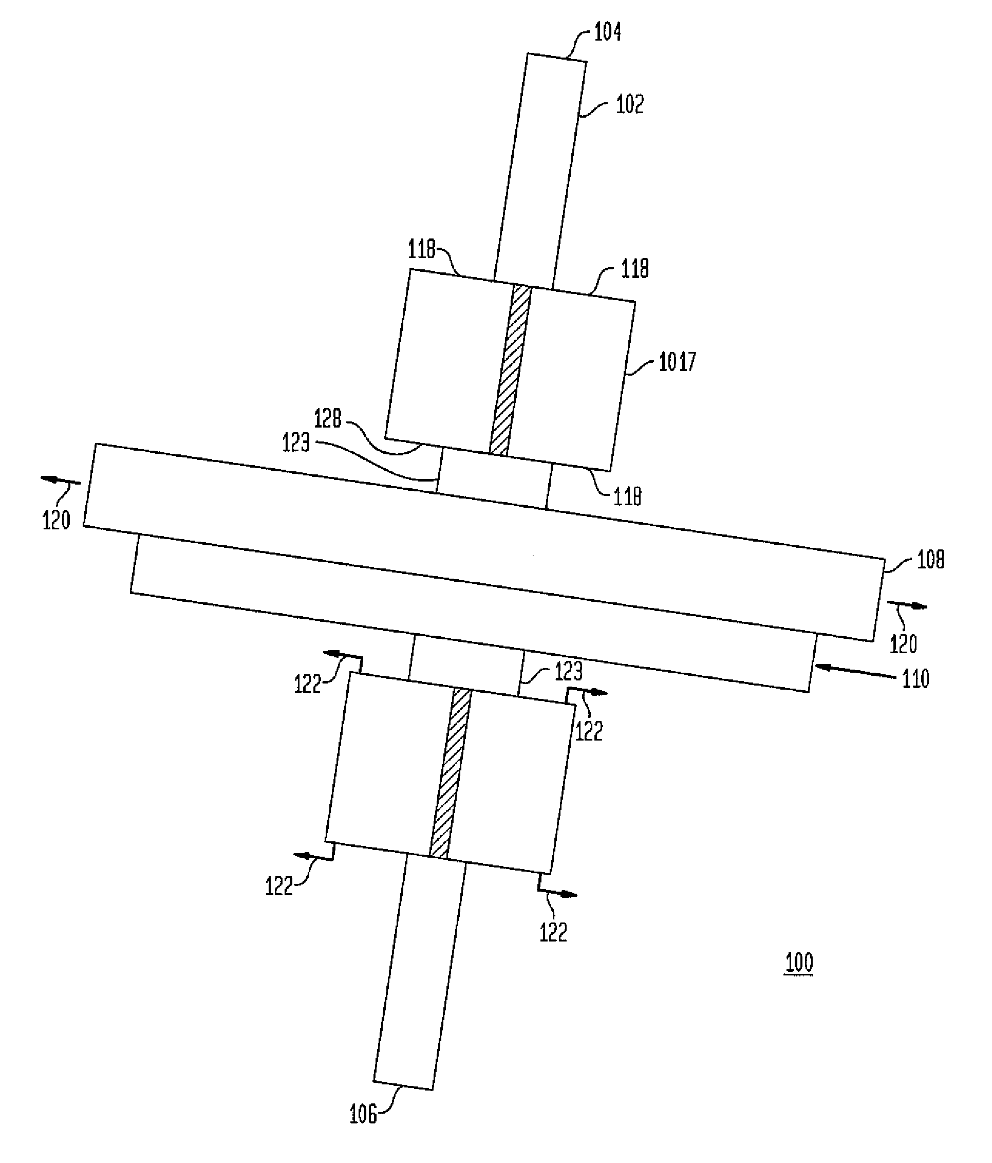
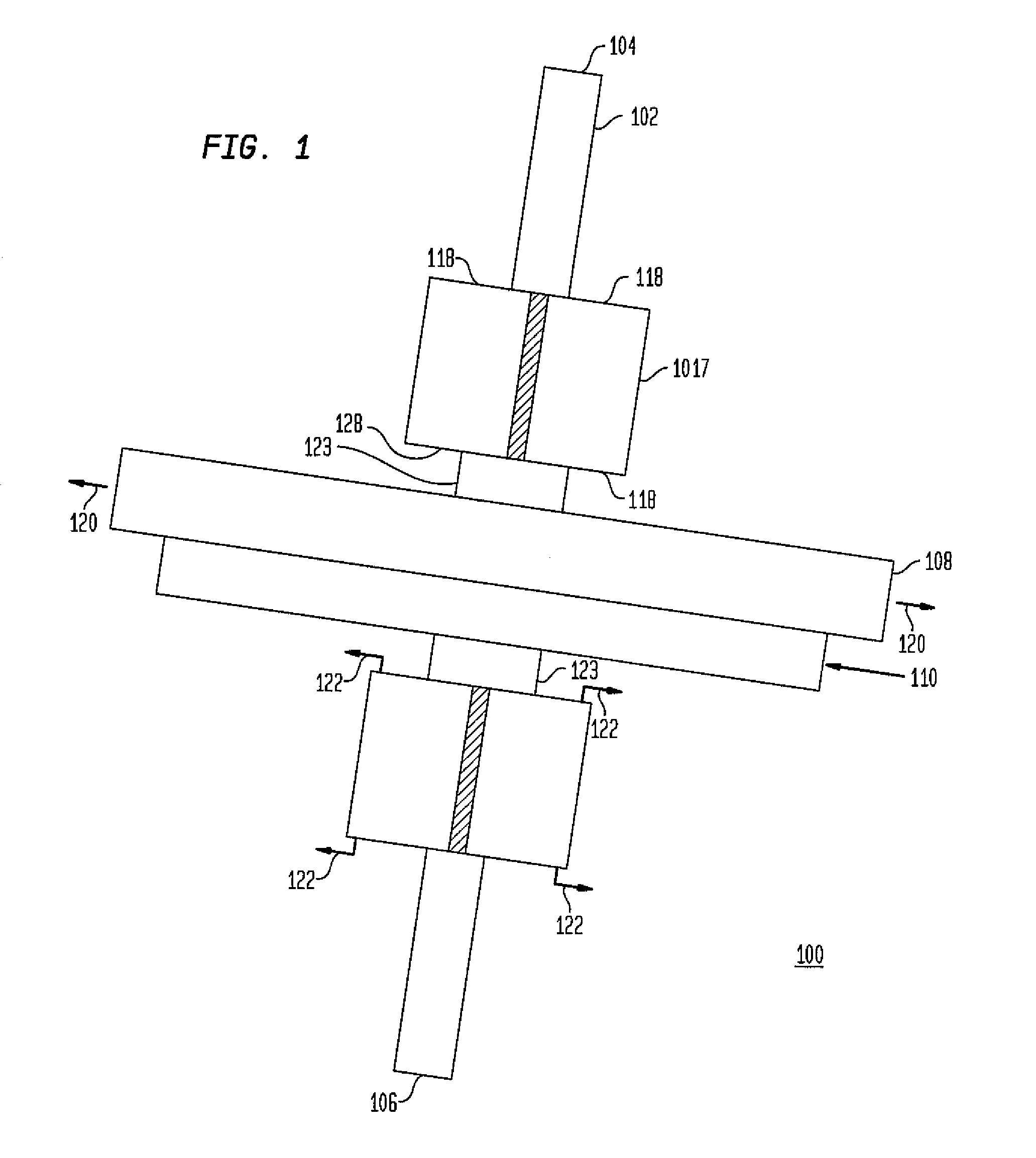
[0029]In one other additional aspect, the rotation of the rotatable centrifuge rotor acts upon the sonic gas flow through the linear nozzle and gas skimmer system with centrifugal force that is in relation to the radius of the overall centrifuge rotor and to the rotation speed of the rotatable centrifuge rotor. The addition of the centrifugal force from the rotatable centrifuge rotor enhances or augments the effective force applied to the sonic gas flow at its core that is proceeding from the convergent nozzle(s) and through the critical throats of the first and second gas skimmer(s) in this manner the centrifigal acceleration enhances the separation effects at the convergent nozzle. The addition of the centrifugal force due to the rotation of the centrifuge rotor adds pressure to the sonic gas beam flow in an increasing amount in relation to the radius of the centrifuge rotor. In applications where phase change occurs through the nozzle skimmer arrangements, the heavier, liquid phase separation is also enhanced based upon the mass difference within the centrifugal field.
[0033]In a second additional aspect, the formation of the integrated convergent-divergent nozzle, followed by an expansion zone, and further followed by a gas skimmer, all built in a curved relationship that is perpendicular to the radial vector of the rotor, causes the gas flow to have additional forces acting upon it. The use of a convergent-divergent nozzle allows for the compression and subsequent expansion of the gas beam to reach an elevated sonic velocity in a range of from 1.5 to 3.5 mach. With the gas beam at its current mach value flowing along a curved radius of a separation nozzle, a first centripetal acceleration is imposed on the gas stream due to the supersonic velocity of the gas beam and the curve of the flow path. A second force that augments the centrifugal acceleration is imposed on the entire nozzle structure, including the gas stream flowing through the nozzle structure. This additional centrifugal force stems from the rotation of the centrifuge rotor and is imparted at the curved boundary wall of the nozzle chamber. In one aspect, the centrifugal force from the rotation of the rotor enhances the separation forces imparted by the gas flow. In a second aspect, the rotation of the rotor services to modulate the separation forces imparted by the gas flow whereby the imposed acceleration due to the rotation of the rotor urges the heavier mass away from the curved boundary wall of the nozzle chamber when the curved boundary wall is concave away from the center of rotation of the rotor disk. Further, beyond the outlet of the convergent-divergent nozzle, an expansion zone is formed extending toward the axis of rotation that allows expansion fraction to move in one radial direction. Finally, the skimmer distance from the convergent-divergent nozzle outlet is longer in distance when compared to a linear design for a nozzle and gas skimmer system by virtue of the circumferential flow path, thereby allowing longer exposure to the centrifugal force.
[0038]In another aspect, the invention includes a method for increasing centrifugal pressure during the separation process by forward high velocity flow along a curved path while the centrifuge rotor is rotating. In this method, concentration of the flow due to centripetal acceleration induces a pressure applied in the direction of the periphery of the curved path, and during the expansion phase in the stagnation zone, lighter specie diffuse toward the axis of rotation of the centrifuge rotor during subsequent pressure and temperature release, concurrently the rotation of the centrifuge rotor adds pressure forcing the flow toward the curved boundary wall, enhancing the concentration of the heavier specie and diffusion of the lighter specie toward the center of rotation. In this aspect, the curvature of the nozzle is concave toward the center of the rotor center of rotation to enhance separation effects. This added pressure energy is an added factor when compared to the Becker separation nozzle system, minimizing boundary flow dilution during the flow process.

Problems solved by technology

Whereas accepted separation technology is now used or is available, capital or energy expense is prohibitive so that acceptable production is not viable.
The use of the centrifuge method for isotope separation was first suggested in 1919, but efforts in this direction were unsuccessful until 1934, when J. W. Beams and co-workers at the University of Virginia applied a vacuum ultracentrifuge to the separation of chlorine isotopes.
Although the separation factors obtainable from the centrifuge method are large compared to gaseous diffusion, several cascade stages are still required to produce even LEU material.
Furthermore, the throughput of a single centrifuge is usually small, which leads to rather small separative capacities for typical centrifuges.
1. It is necessary to establish a circular flow pattern within the centrifuge to recirculate the gas mixture because the separation factor of the centrifuge is determined by the ratio of isotopic abundances at the axis of rotation and at the centrifuge wall.
2. Due to the extremely high speeds necessary to induce meaningful separation, the centrifuge must be precisely machined and balanced and in most cases requires operation in a vacuum system to reduce aerodynamic drag and use of magnetic bearings to reduce friction and vibrations. Further, the high rotational speeds results in significant mechanical stresses on the centrifuge wall requiring the use of exotic materials and fabrication techniques to avoid rupture.
4. The pressure differential between the center of the rotor and the outer wall drives the diffusion rate and thus the theoretical efficiency of the centrifuge. However, it also defines the pressure applied to the gas at the outer wall of the centrifuge and if improperly constructed, the large induced pressure may cause the gas to sublimate and condense on the wall of the centrifuge. To avoid this, the center of the centrifuge must be held at a vacuum, significantly limiting the overall throughput of the centrifuge.
Production of these tiny nozzles by manufacturing is technically demanding, and the overall process typically includes stages having multiple vessels containing hundreds of separation elements, gas distribution manifolds, gas coolers to remove the heat of compression, and centrifugal compressors to pressurize the flow.
In many cases the cut gas must dominate the flow, thereby reducing the overall separation efficiency and throughput of the system.
1. The small size of the curvature wall requires that the nozzle and skimmer components are also minute in size, requiring the components be made of foil material and bonded to assemble even one nozzle. Nano-fabrication is required to form the nozzles, with specifications to the 0.001 mm tolerance.
2. The operating pressure of the process gas is at several bar, usually below 6 bar. The addition of specialized compressors in the cascade add energy to the operating costs to maintain the process at separation pressure.
3. The flow stream along the curvature wall has little if any centrifugal force acting on that streamline, so the 95 / 5 mixture along the curvature wall dilutes the concentrating heavy isotope stream at extraction, thereby reducing the separation factor by dilution.
4. To reduce the cost of the processing, the add-in hydrogen gas must be cleaned at the end of the process for reflux back into the system, adding another separation process to the cascade.
Due to the small degree of separation caused by a single probe, the method has not progressed to any commercial degree.

Method used


Image

  • Device and Method For Particle Separation
  • Device and Method For Particle Separation
  • Device and Method For Particle Separation

Examples


second embodiment

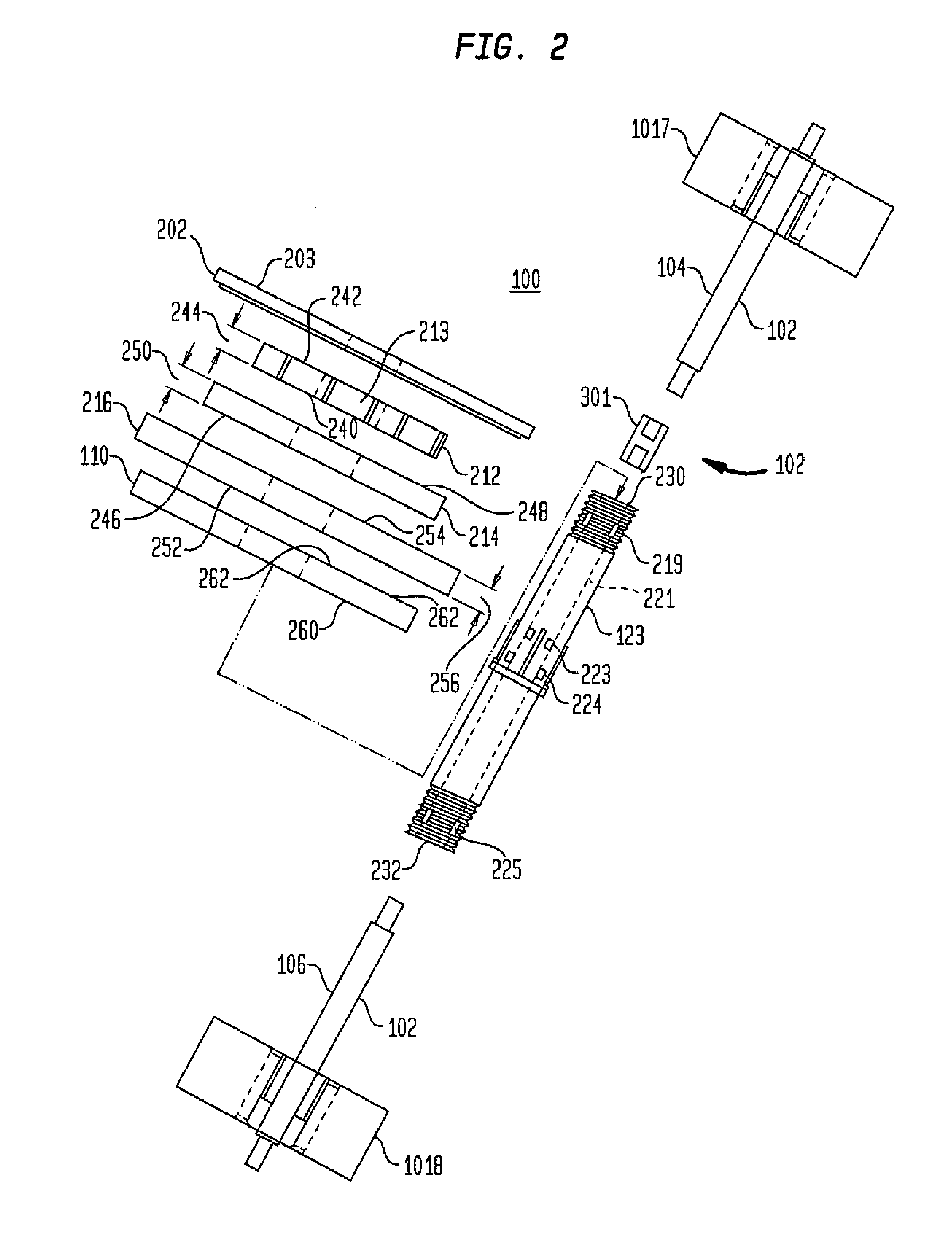
[0067]Embodiments of the present device and method are referred to herein generally as a, “separation device.” Exemplary embodiments of the separation device include a centrifuge rotor configured in multiple embodiments, including a linear nozzle-gas skimmer system, a curved nozzle system, or combinations thereof. As used herein, the terms “exemplary” indicates a sample or example. It is not indicative of preference over other aspects or embodiments. An embodiment of the linear nozzle-gas skimmer system uses a separation configuration having a convergent nozzle followed by a first gas skimmer and followed by a second gas skimmer arranged to correlate and operate in a rotatable centrifuge rotor. the curved nozzle based separation device uses a nozzle insert, an inlet mouth, a nozzle throat connected to a divergent outlet via a concave divergent nozzle, and a skimmer throat. As used herein, the embodiments of the separation configurations with a linear nozzle-gas skimmer, curved nozzl...

first embodiment

[0084]The base and second skimmer ring 216 has an interior wall 501 extending above the bottom surface 522 and positioned between the outer edge of the first skimmer receptor 508 and the outer wall 502. A plurality of second critical throats 518 are located at regular intervals along the interior wall. As shown in FIG. 5B, in one embodiment, the interior wall 512 is composed of a plurality of adjacent, generally block-U shaped, walls that together form a plurality of apex skimmers 524, also referred to herein as a type of or simply as an V-point skimmer, at the intersection of two side walls 514, 516. A second critical throat 518 is formed at each inverted V point, or apex skimmer 524 by two side walls 514, 516, and again, the two side walls 514, 516 act as deflection surfaces for the oncoming gas expansion from the critical throat 616, and the angle of deflection for side walls 514, 516 are in a half-angle range of from about 12° to about 24°. The apex skimmer 524 of the base and s...


PUM

PropertyMeasurementUnit
radiusaaaaaaaaaa
speedaaaaaaaaaa
pressureaaaaaaaaaa

Abstract

A separation device with a gas inlet port that accepts an inlet gas. The inlet gas is composed of a mixture of at least two separable particle components with each component having a different mass. A rotating separation rotor accepts the inlet gas and uses a separator to substantially separate the gas according to mass into two fractions, a heavier and a lighter fraction. One of the fractions is passed to a second separator that further separates that fraction into another two fractions consisting of heavier and lighter fractions. The desired fractions are collected and exhausted from the separation device for use.

Description

CROSS-REFERENCE TO RELATED APPLICATIONS [0001]This application claims the benefit of U.S. Application No. 60 / 870,767, filed Dec. 19, 2006.BACKGROUND OF THE INVENTION[0002]1. Technical Field[0003]The present invention relates to a gas specie and aerosolized-gas mixture particle separation device and process, more generally described as a separation device to separate a gas mixture, or a gas with aerosolized mixture into its heavy and light components by mass differences through a combination of supersonic expansion, core flow collimation, and differential diffusion from a pressure gradient in a centrifugal field.[0004]2. Background Art[0005]Key energy and chemical industries currently require advanced gas separation technologies to be developed so that efficient production of critical products can be realized. Whereas accepted separation technology is now used or is available, capital or energy expense is prohibitive so that acceptable production is not viable. Generally the requirem...

Claims


Application Information

Patent Timeline
Patent Type & Authority Applications(United States)
IPC IPC(8): B01D53/24
CPCB01D45/14B01D53/24B04B5/08B01D2258/06B01D59/20
Inventor BLOOM, MICHAEL R.
Owner TENOROC
Learn More