Cardiac valve prosthesis system

a prosthesis system and valve technology, applied in the field of cardiac valve prosthesis systems, can solve the problems of obstructing blood flow out of the heart, valves can become partially shut, valves can become leaky,

Active Publication Date: 2011-05-26
NVT
View PDF12 Cites 111 Cited by
  • Summary
  • Abstract
  • Description
  • Claims
  • Application Information

AI Technical Summary

Benefits of technology

[0047]connecting the stented valve element and the anchoring element by ligament-like connecting means, such, that a connecting region between the stented valve element and the anchoring element is formed, which is generally free from foreign material.

Problems solved by technology

The valve can either become leaky, i.e. regurgitant or insufficient, in which case the aortic valve is incompetent and blood flows passively back to the heart in the wrong direction.
Further, the valve can become partially shut, i.e. stenotic, in which case the valve fails to open fully, thereby obstructing blood flow out from the heart.
Besides the physical stress associated with this operation, there is a risk of death or serious complications from open heart surgery, in particular depending on the health and age of the patient.
Whereas mechanical valves generally are designed to outlast the patient, they have the drawback that due to their material there is an increased risk of blood clots forming, which may only be prevented by a constant anti-coagulant therapy, which makes the patient more prone to bleeding.
Nevertheless, a major disadvantage of the valves of the state of the art is their insufficient capability to be securely anchored in place of the valve to be replaced with the artificial valve.
Further, many cardiac valve replacement devices do not comprise an element by means of which the artificial valve can be sufficiently secured to the place of the natural valve that is intended to be replaced.
Thus, with such cardiac valves of the state of the art there is the danger of the valve migrating into the vessel and thereby not fulfilling the requirements of a replacement valve any longer.
On the other hand, in order to provide for an secure anchoring of the valve replacement device in a vessel, some of the cardiac valve replacements known in the state of the art represent stiff and bulky devices which is why such cardiac valve replacements often lead to vessel anatomy modifications and consequently to valve malfunctions.

Method used


Image

  • Cardiac valve prosthesis system
  • Cardiac valve prosthesis system
  • Cardiac valve prosthesis system

Examples


Embodiment Construction

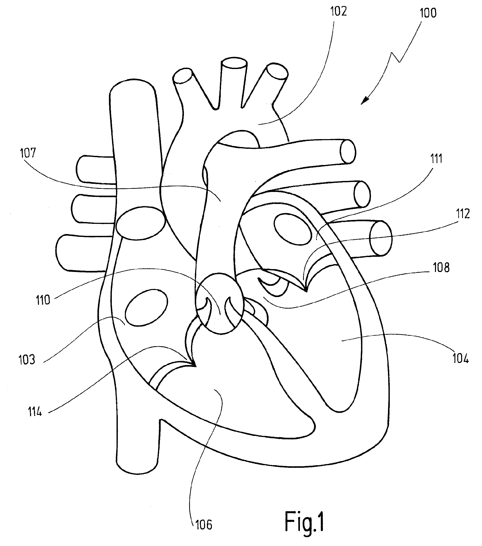
[0060]In FIG. 1, reference number 100 designates a human heart, with the aorta indicated with 102, the left ventricle with 104 and the right ventricle with 106. The four valves of the heart 100 are the aortic valve 108, lying between the left ventricle 104 and the aorta 102, the pulmonic valve 110, lying between the right ventricle 106 and the pulmonary artery 107, the mitral valve 112, lying between the left ventricle 104 and the left atrium 111, and the tricuspid valve 114, lying between the right atrium 113 and the right ventricle 106.

[0061]When during ventricular systole the pressure in the left ventricle 104 rises above the pressure in the aorta 102, the aortic valve 108 opens, allowing blood to exit the left ventricle 104 into the aorta 102. When ventricular systole ends, pressure in the left ventricle 104 rapidly decreases, whereby the aortic pressure forces the aortic valve 108 to close.

[0062]In patients with a diseased and / or malfunctioning aortic valve 108, the valve 108 h...


PUM

PropertyMeasurementUnit
structuresaaaaaaaaaa
flexibleaaaaaaaaaa
shape-aaaaaaaaaa

Abstract

The present invention concerns a cardiac valve prosthesis system (10; 40) for implantation into the body of a mammal. The prosthesis system (19; 40) comprises a valve (16) mounted on an stent element (18) to form a stented valve element (12), and an anchoring element (14) to be arranged within the aorta of the mammal to be treated with the prosthesis and spaced-apart form the stented valve element (12). Further, the anchoring element (14) comprises a cylindrical tube element composed of fabric (22) supported by a metal mesh, and the stented valve element (12) and the anchoring element (14) represent two constructional distinctive elements being associated by ligament-like connecting means (30; 50), such, that the connecting region (28) between the stented valve element (12) and the anchoring element (14) is generally free from foreign material.

Description

CROSS REFERENCES TO RELATED APPLICATIONS[0001]This application is a continuation of international patent application PCT / EP2008 / 005868, filed on Jul. 17, 2008, designating the U.S., which international patent application has been published in English language, and which entire content is incorporated herein by reference.BACKGROUND OF THE INVENTION[0002]The present invention relates to a cardiac valve prosthesis system for implantation into the body of a mammal, comprising a valve mounted on a stent element to form a stented valve element, and an anchoring element to be arranged within the aorta and spaced-apart form the stented valve element.[0003]Valve prosthesis systems of this kind are usually used for replacing damaged, mal- or nonfunctioning cardiac valves. In the heart, cardiac valves maintain the unidirectional flow of blood by opening and closing depending on the difference in pressure on each side.[0004]Besides the valve of the coronary sinus and the valve of the inferior v...

Claims


Application Information

Patent Timeline
Patent Type & Authority Applications(United States)
IPC IPC(8): A61F2/24B23P11/00
CPCA61F2/2418Y10T29/49405A61F2220/0075A61F2220/0008
Inventor CENTOLA, MARCOS
Owner NVT
Why Eureka
Try Eureka