
Bevel and hypoid gear and method of manufacture

a technology of bevels and gears, applied in the field of net shaped bevels and hypoid gears, can solve the problems of long processing time, high cost, and high cost of gear cutting processes, and achieve the effect of reducing forming process steps, accurate production of net shaped tooth profiles, and improving the surface properties of net shaped gears

Inactive Publication Date: 2011-06-02
GM GLOBAL TECH OPERATIONS LLC
View PDF14 Cites 19 Cited by
  • Summary
  • Abstract
  • Description
  • Claims
  • Application Information

AI Technical Summary

Benefits of technology

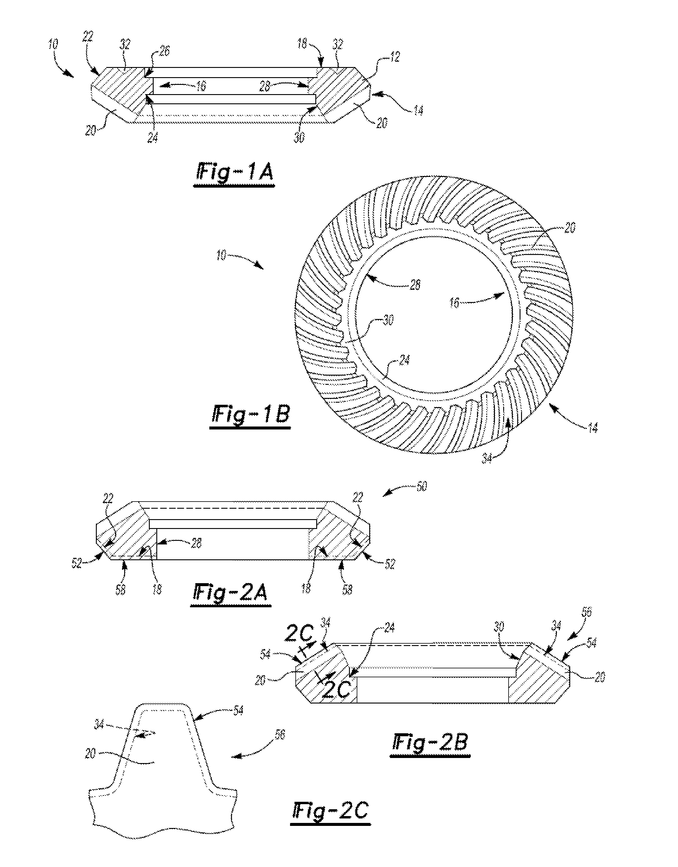
[0013]The annular gear blank, or work piece, is made of powder metal. The annular gear blank is similar in configuration to the net shaped annular gear member. Some portions of the gear blank may be proportionally larger than the corresponding portion of the net shaped gear member depending on the method of incremental deformation. For example, the gear blank portion including a plurality of radially outwardly extending gear teeth, may be proportionally larger than the net shaped gear tooth profile of the net shaped gear member. These proportionally larger portions, during incremental deformation, are subject to preferential or selective compaction and densification to develop desirable mechanical properties, for example, improved surface finish, increased hardness, toughness or strength, reduced grain size, preferred grain orientation, higher load carrying capacity and higher wear resistance.
[0018]Alternatively, the method of incremental deformation may be one of roll forming, where at least two axially rotating tools deform generally opposite sides of an annular gear blank. During the forming process at least one of the tools moves radially and at least one of the tools may move axially. The movement of the tools may be synchronized during the forming sequence, especially as required to accurately produce the net shaped tooth profile with a tool that includes features which are a mirror or counterpart image or conjugate of features of the net shaped tooth profile and gear tooth spacing. After roll forming, the net shaped surfaces of the gear, including the gear tooth surface, may be finished by additional processing, such as lapping, coining, rolling, burnishing or heat treatment, or a combination thereof, for example, to further improve the surface properties of the net shaped gear.
[0019]Advantages of current invention include, for example, a reduction of forming process steps, higher process yields, lower forming pressures compared with other forming methods contributing energy savings, minimal material waste, extended equipment and tooling longevity, reduced tooling costs and reduced work in process inventory from raw material to finished product. Further advantages of the current invention may include optimization of gear teeth characteristics such as strength, density, toughness, hardness, grain size and orientation, wear resistance and noise and vibration reduction.

Problems solved by technology

Gear cutting processes are disadvantaged by high cost, lengthy processing time, poor yields, cutting allowance material waste and reduced tooth surface strength.
Gear forging processes are disadvantaged by multiple forging and reheating steps during which scale formation and decarburization of the steel may occur, the use of high forming pressures resulting in low tool life and post-forging finishing operations including sizing, machining and heat treatment that can result in lengthy processing time and high cost.

Method used


Image

  • Bevel and hypoid gear and method of manufacture
  • Bevel and hypoid gear and method of manufacture
  • Bevel and hypoid gear and method of manufacture

Examples


first and second embodiments

Orbital Forming

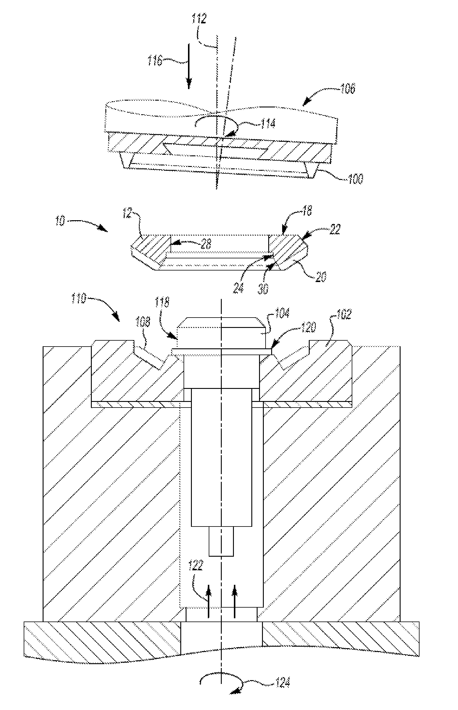
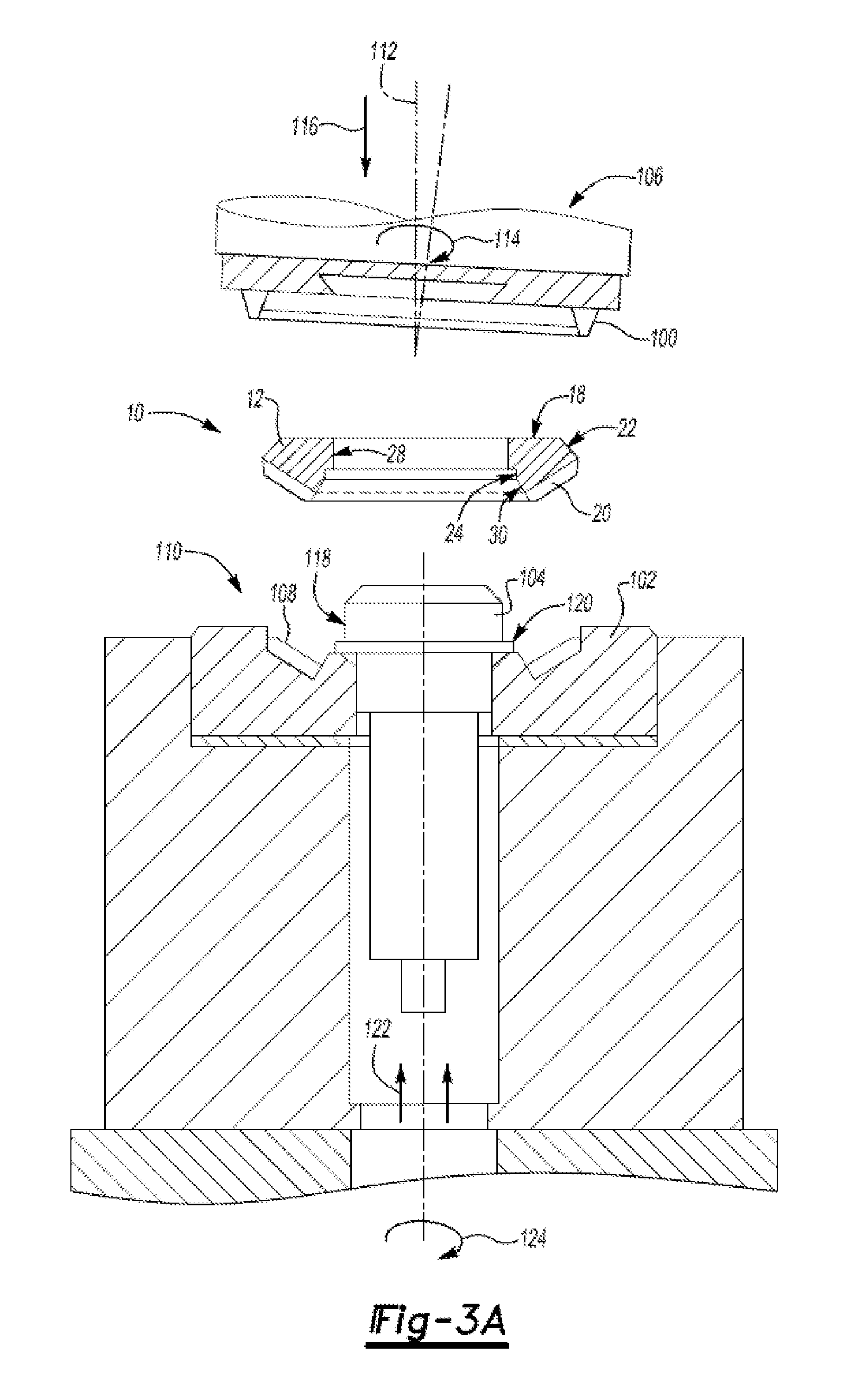
[0055]In a first embodiment of incremental deformation, and referring now to FIG. 3A, there is shown gear member 10 formed by orbital forging, also known as orbital forming. Gear member 10 is formed by incrementally deforming a gear blank 50 (not shown, see FIG. 2A) by repeatedly orbitally applying sufficient pressure locally to base portion 58 and transition portion 52 (shown in FIG. 2A) of blank 50. The pressure to deform gear blank 50 is applied by a first tool 100 or tool assembly 106 (where hereinafter “tool 100” refers to either a tool 100 or tool assembly 106) progressing axially 116 toward a second tool 102 or tool assembly 110 (where hereinafter “tool 102” refers to either a tool 102 or tool assembly 110). A first tool 100 is fixed axially 112 and moves in at least one of an orbital, spiral, planetary or straight-line motion 114 to repeatedly exert pressure on gear blank 50, causing blank 50 to deform against the profile of first tool 100 and into the cavity ...

third and fourth embodiments

Radially Roll Forming

[0067]In a third embodiment of incremental deformation, and referring now to FIG. 4A, there is shown gear member 10 formed by radially roll forming, also known as radially roll forging. The gear blank 56 (not shown, see FIGS. 2B and 2C) is positioned on platen tool 304 prior to forming and may be fixed to or positioned on platen tool 304 by a method or mechanism familiar to those skilled in the art. Such a method may include fabricating surface features 32, shown in FIG. 1A, which may be configured, for example, as dimples, grooves, slots, or holes on gear blank 56 during the fabrication of gear blank 56, with surface features 32 placed at increments on base surface 18 surface of blank 56 to coincide in position with holes or slots 310 in platen tool 304. Holes or slots 310 may contain pins, dowels, bolts or other similar tool details (not shown) which, when such details are inserted or fastened into surface features 32 of gear blank 56, function to retain gear ...


PUM

PropertyMeasurementUnit
Grain sizeaaaaaaaaaa
Pressureaaaaaaaaaa
Wear resistanceaaaaaaaaaa

Abstract

Bevel and hypoid gears are used in power transmissions including automotive applications. Provided is a net shaped bevel or hypoid gear having a generally annular gear body including a plurality of radially outwardly extending gear teeth formed from a generally annular blank made of powdered metal. Also provided is a method for manufacturing a net shaped bevel or hypoid gear including the steps of providing and optionally heat treating a generally ring-shaped or annular blank made of metal powder, then incrementally deforming the blank by orbitally forming or roll forming to produce a net shaped gear member with a plurality of outwardly extending gear teeth, which may be of a bevel or hypoid type.

Description

TECHNICAL FIELD[0001]The present invention relates to net shaped bevel and hypoid gears, more specifically to a bevel or hypoid gear formed from metal powder and a method for manufacturing same.BACKGROUND OF THE INVENTION[0002]Bevel ring gears are well known and commonly used in power transmission applications. Among known bevel gears are helical bevel gears, spiral bevel gears, hypoid gears and the like. Spiral bevel ring gears typically have a generally annular gear body having a surface including a plurality of radially outwardly extending gear teeth. The form of the gear tooth may be, for example, one of a straight, spiral and hypoid type.[0003]While hypoid gears are similar in their general form to spiral bevel gears, hypoid gears differ by having spiral teeth that are curved and oblique, where the pitch surface of the tooth is a hyperboloid of revolution, hence the name. Hypoid gears operate on non-intersecting axes, which may be at right angles or otherwise. Hypoid gears are ...

Claims


Application Information

Patent Timeline
IPC IPC(8): B23P15/14F16H55/17
CPCB22F5/08Y10T74/19958Y10T29/49476F16H55/06
Inventor LEV, LEONID C.AKSENOV, LEONID B.VOSTROV, VLADIMIR N.
Owner GM GLOBAL TECH OPERATIONS LLC
Learn More