Plasma processing apparatus

a processing apparatus and plasma technology, applied in the field of plasma processing apparatus, can solve the problems of difficult rapid change of coolant temperature, low temperature control responsiveness, deterioration of semiconductor device or display device production yield, etc., to improve reliability and reproducibility of plasma process, improve the impedance of high frequency noise, and improve the effect of plasma process reliability

Active Publication Date: 2011-06-02
TOKYO ELECTRON LTD
View PDF9 Cites 23 Cited by
  • Summary
  • Abstract
  • Description
  • Claims
  • Application Information

AI Technical Summary

Benefits of technology

[0035]In accordance with the plasma processing apparatus of the seventh aspect, in the filter provided on the line that connects the external circuit of the signal system or the power system with the electric member within the processing chamber that performs the plasma process therein, the distributed constant line is formed between the first conductor and the tube-shaped second conductor that accommodates or surrounds the first conductor. The distributed constant line has impedance characteristic of forming parallel resonance at regular multiple resonance frequencies. By the parallel resonance frequency controller, one of the parallel resonance frequencies is set to be equal to or approximate to a frequency of the high frequency noise to be blocked, so that the distributed constant line can provide sufficiently high impedance for the high frequency noise. Therefore, the power feed circuit may be securely protected, and reproducibility and reliability of the plasma process may be improved
[0036]In accordance with the plasma processing apparatus of the present disclosure, with the configuration and operation as described above, reliability and reproducibility of the plasma process can be improved by efficiently, stably and securely blocking a high frequency noise (especially, a plurality of high frequency noises having different frequencies) flowing into a line such as a power feed line or a signal line from electric members including a high frequency electrode within a processing chamber. Further, a high frequency blocking function can be improved by adjusting the parallel resonance frequency.

Problems solved by technology

If the temperature control of a substrate is not appropriately performed, uniformity of a reaction on a substrate surface and uniformity of process characteristics may not be secured, resulting in deterioration of a production yield of semiconductor devices or display devices.
However, in this method of using such a chiller mechanism, it has been difficult to rapidly change a temperature of the coolant.
Further, since responsiveness in temperature control is low, a temperature variation, a temperature increase or a temperature decrease may not be performed at a high speed.
Meanwhile, in case that a lower electrode high-frequency application type in which a high frequency power supply is connected to the susceptor (lower electrode) is used for a plasma control and, at the same time, the heater mechanism in which the heating member is embedded in the susceptor is used for a temperature control, a part of a high frequency power applied to the susceptor from the high frequency power supply may reach a heater power supply as a noise via the heating member and a heater power feed line, resulting in deterioration of an operation and a performance of the heater power supply.
Therefore, if a high frequency noise is introduced therein, the heater may suffer an operation failure.
However, it was found out that in case of employing a lower electrode dual frequency application type in which both a high frequency power of a relatively low frequency (typically, about 13.56 MHz or less) for ion attraction and a high frequency power of a relatively high frequency (typically, about 27 MHz or more) for plasma generation are applied to the susceptor, it is difficult to stably and securely block the high frequency noise having a relatively high frequency by using the filter having the above-described configuration.
To be specific, if the frequency of the high frequency power for plasma generation is increased (typically, if it is set to be about 60 MHz or higher) in order to obtain high density plasma under a low pressure, an impedance characteristic of the filter for such a high frequency range may become non-uniform.
The non-uniformity of the filter characteristic may have adverse effect on reliability and reproducibility of a plasma process, and, thus, a difference in process performance may be caused in a plasma processing apparatus for mass production.
With this filter configuration, however, an impedance characteristic may be changed complicatedly because of self-resonance of a coil included in each LC parallel resonance circuit or a mutual interference between the adjacent LC parallel resonance circuits.

Method used


Image

  • Plasma processing apparatus
  • Plasma processing apparatus
  • Plasma processing apparatus

Examples


first experimental example

[0085][First Experimental Example of Filter]

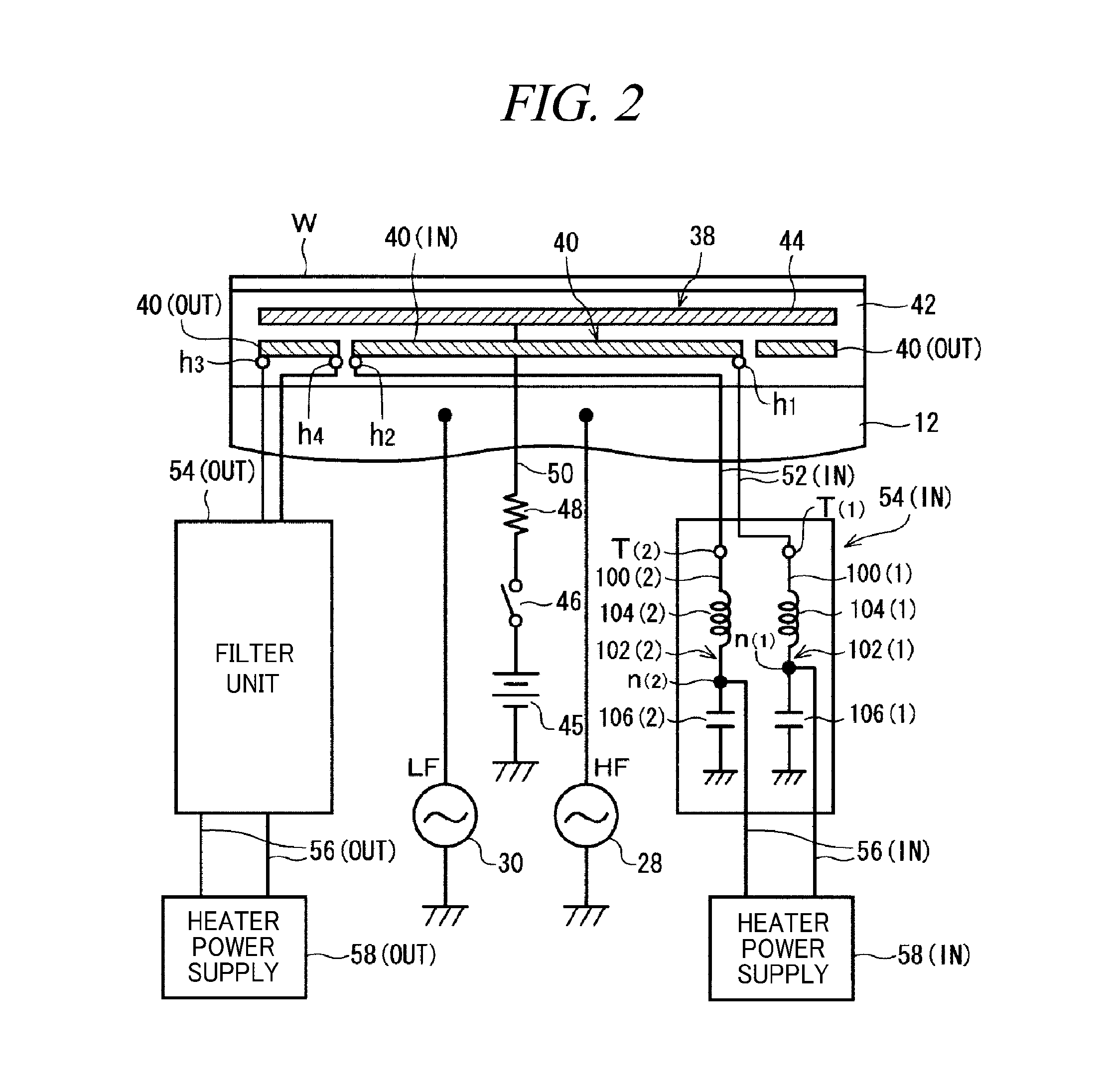
[0086]FIGS. 4 to 7 illustrate a physical structure of a filter unit 54(IN) in accordance with a first experimental example. In the filter unit 54(IN), as shown in FIGS. 4 and 5, a coil 104(1) of a first filter 102(1) and a coil 104(2) of a second filter 102(2) are coaxially provided within a cylindrical outer conductor 110 made of, e.g., aluminum. Further, on an opposite side of filter terminals T(1) and T(2), a capacitor 106(1) of the first filter 102(1) and a capacitor 106(2) of the second filter 102(2) are accommodated together within a capacitor box 112 made of, e.g., aluminum, as shown in FIG. 2. The outer conductor 110 is fixed to a conductive member of a ground potential, e.g., a chamber 10 by screws.

[0087]Each of the coils 104(1) and 104(2) may be an air core coil and has a function as a power feed line through which a sufficiently high current (e.g., about 30 A) flows from a heater power supply 58(IN) into an inner heating wire 40...

second experimental example

[0123][Second Experimental Example of Filter]

[0124]FIG. 15 illustrates a physical structure of a filter unit 54(IN) in accordance with a second experimental example. An inventive feature of the second experimental example lies in that a parallel resonance frequency controller for adjusting a parallel resonance frequency is further included in a filter unit 54(IN) as used in the first experimental example. In the following second experimental example, a configuration of a first filter 102(1) and an operation of a first distributed constant line 120(1) will be described. A configuration of the second filter 102(2) and an operation of a second distributed constant line 120(2) are completely the same as those of the first filter 102(1) and the first distributed constant line 120(1).

[0125]The parallel resonance frequency controller may be configured as a characteristic impedance varying member for partially varying a characteristic impedance of a distributed constant line 120(1) by causi...

third experimental example

[0139][Third Experimental Example of Filter]

[0140]FIG. 17 illustrates a physical structure of a filter unit 54(IN) in accordance with a third experimental example. The third experimental example is a modification example of the above-described second experimental example, and one filter 102(1) includes a plurality of, e.g., two ring members 122. Although the plurality of ring members 122 and 122 may have different shapes, sizes and materials, it may be typically desirable that they have the same shape, size and material.

[0141]The present inventors fabricated the sample filter unit 54(IN) having the aforementioned configuration in accordance with the third experimental example shown in FIG. 17, and an impedance characteristic is measured using a network analyzer as described above, and then the impedance characteristic of the sample product in accordance with third experimental example is compared with that of the sample product in each of the first and second experimental examples.

[...


PUM

PropertyMeasurementUnit
frequencyaaaaaaaaaa
frequencyaaaaaaaaaa
frequencyaaaaaaaaaa

Abstract

A parallel resonance frequency can be adjusted in order to stably and securely block different high frequency noises flowing into a line such as a power feed line or a signal line from electric members including a high frequency electrode within a processing chamber. A filter 102(1) coaxially accommodates a coil 104(1) within a cylindrical outer conductor 110, and a ring member 122 is coaxially installed between the coil 104(1) and the outer conductor 110. The ring-shaped member 122 may be a plate body of a circular ring shape on a plane orthogonal to an axial direction of the outer conductor 110 and made of a conductor such as cupper or aluminum and electrically connected with the outer conductor 110 while electrically insulated from the coil 104(1).

Description

CROSS-REFERENCE TO RELATED APPLICATION[0001]This application claims the benefit of Japanese Patent Application No. 2009-265881 filed on Nov. 24, 2009, and U.S. Provisional Application Ser. No. 61 / 296,285 filed on Jan. 19, 2010, the entire disclosures of which are incorporated herein by reference.FIELD OF THE INVENTION[0002]The present disclosure relates to a plasma processing apparatus for performing a plasma process on a processing target object by using a high frequency power, and more particularly, to a plasma processing apparatus including a filter for blocking a high frequency noise flowing into a line such as a power feed line or a signal line from an electric member such as a high frequency electrode within a processing chamber.BACKGROUND OF THE INVENTION[0003]In microprocessing for manufacturing a semiconductor device or a FPD (Flat Panel Display) using plasma, it is important to control a temperature and a temperature distribution of a substrate as well as a plasma density ...

Claims


Application Information

Patent Timeline
Patent Type & Authority Applications(United States)
IPC IPC(8): C23C16/513
CPCH01J37/32091H05H1/46H01J37/32522H01J37/32174H01J37/32192
Inventor YAMAZAWA, YOHEIMATSUMOTO, NAOKIIWASAKI, MASAHIDEOKUNISHI, NAOHIKO
Owner TOKYO ELECTRON LTD
Why Eureka
Try Eureka