
Electric heating element for insoles

a technology of heating element and insole, which is applied in the field of electric heating element for insoles, can solve the problems of inability to trim the insole, risk of damaging or destroying the heating element, and inconvenient use, so as to enhance the life of the power pack, enhance the comfort of the wearer, and enhance the effect of heat distribution

Inactive Publication Date: 2011-06-02
HOTRONIC INT
View PDF6 Cites 10 Cited by
  • Summary
  • Abstract
  • Description
  • Claims
  • Application Information

AI Technical Summary

Benefits of technology

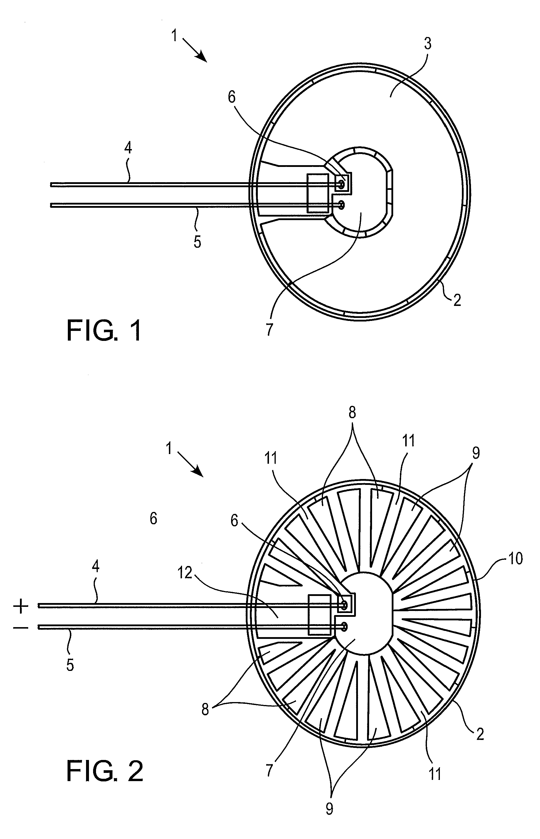
[0006]In an embodiment of the electric heating element the heating means comprises at least one flat, planar heating area which is covered with an electrically resistive coating. The electrically resistive coating may be applied to the flat sheet of material in a rather thin coating, so that the overall thickness of the electric heating element may be kept rather low. The electrically resistive coating is very homogenous and supports a uniform production of heat when electric direct current flows therethrough.
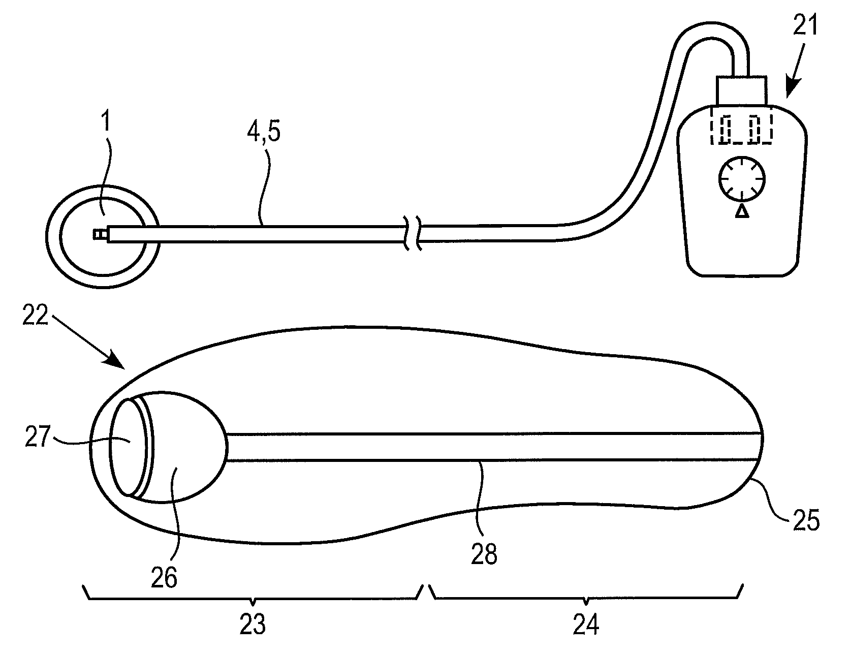
[0007]In another embodiment of the electric heating element the heating means comprises a number of said heating areas which are all evenly covered with the electrically resistive coating, and the heating areas are electrically connected with each other in series. In an alternative embodiment of the electric heating element the heating means again comprises a number of said heating areas which are covered with said electrically resistive coating. In this alternative embodiment the heating areas are connected with each other in electrically parallel configuration. Both, the serial and the parallel arrangement, allow for an easy trimming of the heating areas, which are configured as planar resistors. The trimming of the planar resistors may be accomplished, e.g., with a laser. It may be performed during the manufacturing of the heating element, in order to achieve very steady result. The trimming of the planar resistors may also be used to produce planar resistors having different resistance values, and thus to achieve heating areas which produce more or less heat across the surface of the heating element.
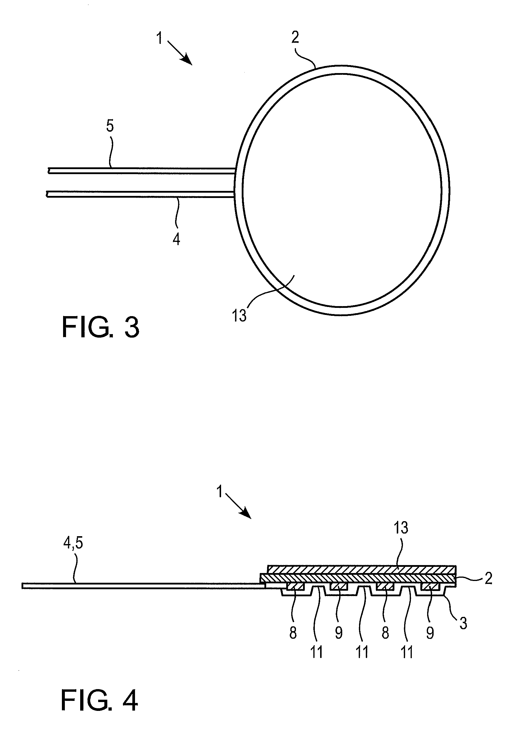
[0013]A further embodiment of the electric heating element according to the invention comprises a copper layer evenly distributed across a surface of said sheet material which is opposite to said surface bearing said electrodes. The copper layer enhances the even distribution of the heat produced by the resistor fields on the opposite side of the sheet material, i.e. the piece of printed circuit board.
[0014]An electric heating insole system for use in footwear according to the invention comprises a flexible, cushioned footwear insole of extended length with a forefoot region and a heel region. The insole has a bottom surface which is provided with a closable receptacle for accommodating an electric heating element in accordance with any one of the embodiments described above. The insole is further being provided in the bottom surface with a channel extending from the receptacle for the heating element to the heel region for accommodating a flexible electric power cable which is adapted to be connected with an electric power source for direct current. In the electric heating insole system according to the invention the insole and the heating element are separate components which may be assembled to a system as desired. The retailer needs to keep on stock only a limited number of heating elements which all have a standardized size. The insoles may be shaped to any foot size, or they may be provided only, e.g., in small, medium, and large size. The retailer or the customer may upon sale trim the insole to the exact required size and shape in accordance with the designated footwear. This is an improvement for both, the retailer and the customer. The retailer need not keep in stock large numbers of insoles and heating elements, and the retailer or the customer may trim the insole exactly to the required shape, which enhances comfort for the wearer of the footwear.
[0015]In an embodiment of the electric heating insole system the electric power source is a battery power pack comprising at least one rechargeable battery and further being provided with a control circuit. The control circuit controls temperature and regulates the power supply accordingly. It further may be provided with a power management system, which enhances the life of the power pack. The rechargeability of the battery pack takes into account environmental aspects.

Problems solved by technology

This may result in discomfort in the extremities, i.e., the feet.
Trimming of the insole is hardly possible because of the danger that the electro-thermal resistance heating structure is damaged or destroyed.
Also the insole may be trimmed fit exactly into the footwear with any risk of damaging or destroying the heating element.
While this known heating insole system proves convenient, both, for the retailer and for the customer, the discrete resistors or like discrete heat producing elements of the heating element, which produce the heat, may become a source of discomfort for the customer.
Also the heat producing elements, which are interconnected in series, form discrete heat sources, which for persons with very sensitive footsoles may seem uncomfortable.

Method used


Image

  • Electric heating element for insoles
  • Electric heating element for insoles
  • Electric heating element for insoles

Examples


Embodiment Construction

[0022]The following description of exemplary embodiments of the invention is for illustrative purposes only and is not intended to limit of the scope of the invention.

[0023]In FIGS. 1 and 2 a heating element is generally designated with reference numeral 1. The heating element comprises a flat material sheet 2 with electrodes 8 and 9 distributed across the surface of the material sheet 2 (FIG. 2). In a specific embodiment the heating element comprises a piece of a printed circuit board, which is made of a sheet of electrically isolating material, usually a fiber reinforced resinous structure, with electric conductors on one of its surfaces. The electric conductors, i.e. the electrodes 8, 9, are established e.g. by appropriate etching of a layer of copper which has been deposited on the basic material sheet 2. At the completed heating element, which is depicted in FIG. 1, the electrodes are entirely covered with an electrically resistive coating 6, such as, e.g., a polymer-resistive ...


PUM


Abstract

There is described an electric heating element for insoles of footwear is provided which comprises a flexible, generally flat sheet of material. The sheet of material is provided across its surface with heating means. The heating means is connected with a number of flat electrodes for electric direct current, and includes positive and negative electrodes which are electrically connectable to a positive and a negative power line, respectively. The heating means is of a planar, continuous configuration and adapted to produce heat when electric direct current flows therethrough.

Description

FIELD OF THE INVENTION[0001]The present invention relates to an electric heating element for insoles as used in footwear. The invention further relates to an electric heating insole system that can be freely installed in footwear and generate a heating function under user control.BACKGROUND OF THE INVENTION[0002]Many sports and other activities are conducted outdoors under cold and perhaps harsh conditions. Examples include but are not limited to snow skiing and snow boarding, ice skating, hinting, ice fishing, etc. Also many professions involve exposure to similar cold conditions. In each circumstance the body will respond to cold temperatures by directing the blood flow such that the core body temperature is maintained. This may result in discomfort in the extremities, i.e., the feet.[0003]From the prior art a number of products are known which are designated to provide warmth and comfort for the feet, among them heating insole systems which may be installed and inserted in footwe...

Claims


Application Information

Patent Timeline
Patent Type & Authority Applications(United States)
IPC IPC(8): H05B3/00A43B7/02A43B7/04A43B3/35
CPCA43B7/04H05B3/34H05B2203/036H05B2203/013H05B2203/017H05B2203/006A43B3/35
Inventor TENIAS, DANIEL LOPEZ
Owner HOTRONIC INT
Learn More