
Flexible circuit board and method for producing same and bend structure of flexible circuit board

a flexible circuit board and flexible technology, applied in the direction of printed circuit manufacturing, printed circuit aspects, conductive pattern formation, etc., can solve the problems of poor strength, no longer usable circuit boards, cracked or broken wiring, etc., and achieve excellent bendability and high durability.

Inactive Publication Date: 2011-06-09
NIPPON STEEL CHEMICAL CO LTD
View PDF6 Cites 46 Cited by
  • Summary
  • Abstract
  • Description
  • Claims
  • Application Information

AI Technical Summary

Benefits of technology

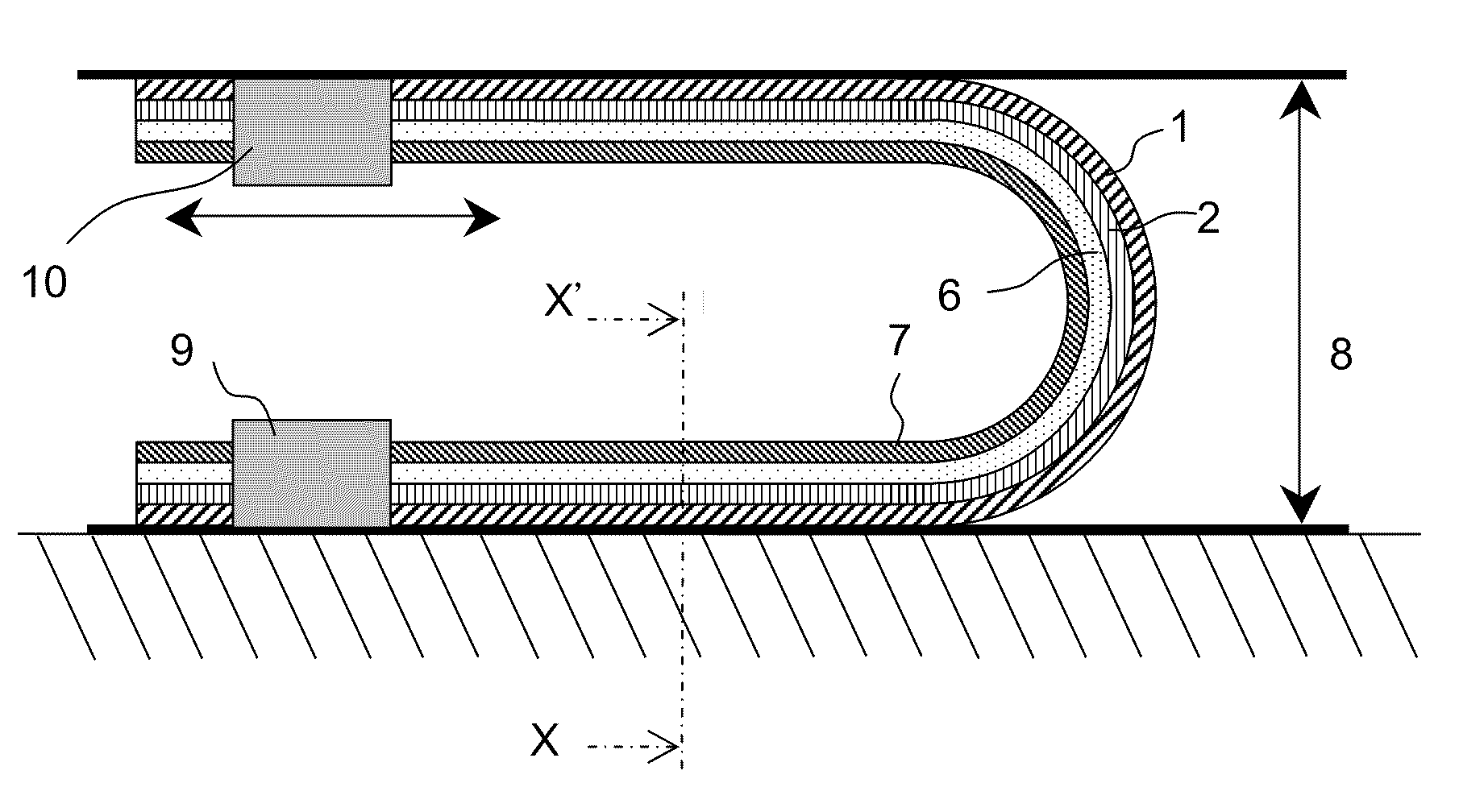
[0034]According to the present invention, when the flexible circuit board is bent, shear slip of the bend portion in a principal distortion direction easily occurs, thereby obtaining functions and effects that breakage is less likely to occur. Further, metal fatigue against repeated distortion is less likely to occur. Besides, metal fatigue against stress is less likely to occur. Therefore, it is possible to provide a flexible circuit board which has a strength capable of resisting repetition of folding or bending at a small curvature radius and exhibits excellent bendability, without being limited in design. As a result, highly-durable electronic devices including a thin mobile phone, a thin display, a hard disk drive, a printer, and a DVD drive may be realized.

Problems solved by technology

In general, the wiring rather than the resin layer is responsible for a defect resulting from poor strength against the repetition of folding or the bending at the small curvature radius.
When the wiring becomes difficult to resist the repetition of folding or the bending, the wiring is cracked or broken in part and becomes no longer usable for a circuit board.
However, in any of such methods, a design of the flexible circuit board is limited.

Method used


Image

  • Flexible circuit board and method for producing same and bend structure of flexible circuit board
  • Flexible circuit board and method for producing same and bend structure of flexible circuit board
  • Flexible circuit board and method for producing same and bend structure of flexible circuit board

Examples


synthesis example 1

[0079]N,N-dimethylacetamide was set in a reaction container which included a thermocouple and an agitator. Nitrogen may be introduced into the reaction container. Next, 2,2-bis [4-(4-aminophenoxy) phenyl]propane (BAPP) was dissolved while being agitated in the reaction container. Then, pyromellitic dianhydride (PMDA) was added. Charging was performed so that a total monomer charge amount was 15 wt %. After that, agitation was continued for three hours to obtain a resin solution of polyamide acid-a. A solution viscosity of the resin solution of polyamide acid-a was 3,000 cps.

synthesis example 2

[0080]N,N-dimethylacetamide was loaded in the reaction container which included a thermocouple and an agitator. Nitrogen may be introduced into the reaction container. Next, 2,2′-dimethyl-4,4′-diaminobiphenyl (m-TB) was charged to the reaction container. Then, 3,3′, 4,4′-biphenyl tetracarboxylic dianhydride (BPDA) and pyromellitic dianhydride (PMDA) were added. Charging was performed so that a total monomer charge amount was 15 wt % and a molar ratio between the respective acid anhydrides (BPDA: PMDA) was 20:80. After that, agitation was continued for three hours to obtain a resin solution of polyamide acid-b. A solution viscosity of the resin solution of polyamide acid-b was 20,000 cps.

example 1

[0081]The polyamide acid solution-a prepared as described above was applied to the copper foil-A and dried (thermoplastic polyimide film having thickness of 2 μm was formed after curing). Then, the polyamide acid-b was applied and dried (low-thermal expansion polyimide film having thickness of 12 μm was formed after curing). After that, the polyamide acid-a was applied and dried (thermoplastic polyimide film having thickness of 2 μm was formed after curing). Then, the copper foil-A was subjected to a heating condition for heating at a temperature in a range of 300° C. to 360° C. for an integral time equal to or longer than five minutes to form a polyimide layer having a three-layer structure. Next, the copper foil-A was cut into a rectangular size which has a length of 250 mm in a rolling direction (MD direction) and a width of 150 mm in a direction (TD direction) orthogonal to the rolling direction, to obtain a one-side copper-clad laminate 4 including the polyimide layer (resin la...


PUM

PropertyMeasurementUnit
thicknessaaaaaaaaaa
thicknessaaaaaaaaaa
thicknessaaaaaaaaaa

Abstract

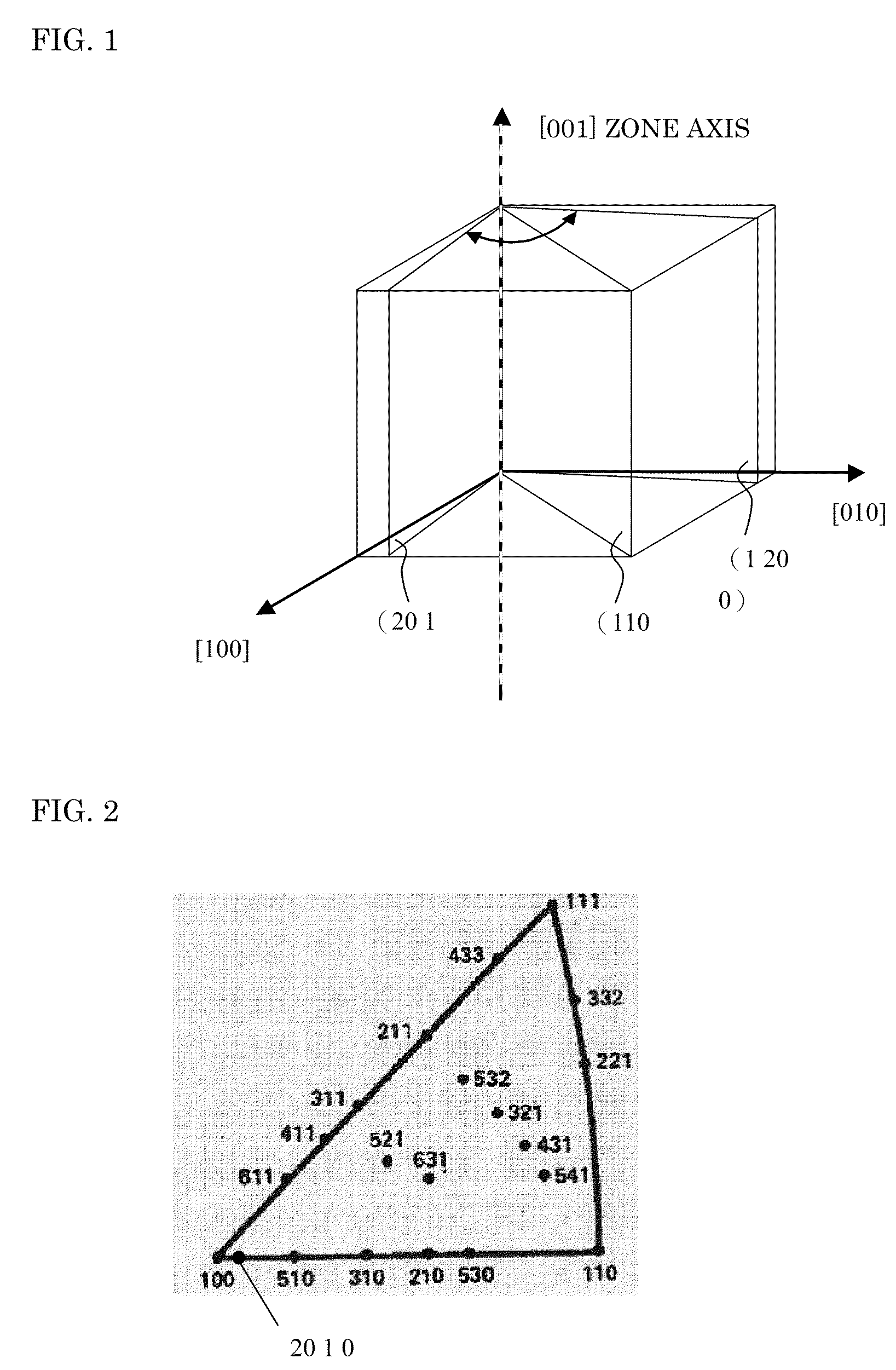
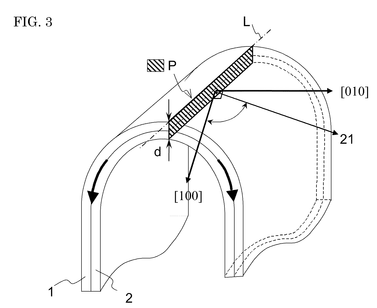
Provided are a flexible circuit board with excellent bendability and durability against hard conditions particularly in a repeated bend portion having a small curvature radius, and a method of producing the same. The flexible circuit board includes a resin layer and a wiring formed of a metal foil and is used with a bend portion provided at least one position of the wiring. The metal foil is made of a metal having a cubic crystal structure, and a cross section of the wiring cut in a thickness direction from a ridge line in the bend portion forms a principal orientation on any one of planes within a range of (20 1 0) to (1 20 0) in a rotation direction from (100) to (110) with [001] set as a zone axis. The wiring is formed so that the metal foil is made of a metal having a cubic crystal structure, and that the ridge line in the bend portion has an angle in a range of 2.9° to 87.1° relative to one of fundamental crystal axes <100> in a surface of the metal foil.

Description

TECHNICAL FIELD[0001]The present invention relates to a flexible circuit board used with a bend portion provided at any position, a method of producing the same, and a bend structure of the flexible circuit board, and more particularly, to a flexible circuit board which is durable against bending and exhibits excellent bendability, a method of producing the same, and a bend structure of the flexible circuit board.BACKGROUND ART[0002]A flexible circuit board (flexible printed board) including a resin layer and a wiring made of a metal foil may be used in a bending state, and thus is widely used for various electronic or electrical devices including a movable portion contained in a hard disk drive, a hinge portion or slide portion of a mobile phone, a head portion of a printer, an optical pickup portion, and a movable portion of a notebook PC. In recent times, particularly, with downsizing and thinning of the devices and an improvement of a function thereof, the flexible circuit board...

Claims


Application Information

Patent Timeline
Patent Type & Authority Applications(United States)
IPC IPC(8): H05K1/09H05K3/00
CPCB21B1/40B21B2003/005C22F1/08H05K1/028Y10T29/49155H05K1/09H05K2201/0355H05K2203/0143H05K1/0393
Inventor HATTORI, KOICHIKIWASAKI, NAOYA
Owner NIPPON STEEL CHEMICAL CO LTD
Learn More