Method and apparatus for controlling particle diameter and particle diameter distribution of emulsion particles in emulsion

a technology of emulsion particles and emulsion, which is applied in the direction of synthetic resin layered products, chemical/physical processes, natural mineral layered products, etc., can solve the problems of water-based medium contaminated by transferred fine particles, significant differences in the properties of obtained emulsions, and differences in spreadability on the skin, so as to achieve easy scale-up and maintenance, easy control, and simple structure

Inactive Publication Date: 2011-06-09
NIPPON OIL CORP
View PDF6 Cites 8 Cited by
  • Summary
  • Abstract
  • Description
  • Claims
  • Application Information

AI Technical Summary

Benefits of technology

[0018]The present invention solves the problems in the conventional continuous emulsification methods and apparatuses. The invention provides a continuous emulsification method and an apparatus used to obtain an emulsion containing liquid droplets having a desired average particle diameter and a desired particle diameter distribution, in particular, a narrow (uniform) particle diameter distribution, suitable for the various applications described above. The method and apparatus are easily controlled and have simple structures, and the scale-up and maintenance thereof are easy. Moreover, the method and apparatus can provide an emulsified product in an amount sufficient for industrial production. It is another object to provide various industrial products, such as microcapsules and polymer fine particles, having a desired average particle diameter and a desired particle diameter distribution, in particular, a narrow (uniform) particle diameter distribution, suitable for the various applications described above. These industrial products are provided using an emulsion obtained by the above method and apparatus.
[0023]In the present invention, an emulsification apparatus having an extremely simple structure is used. The emulsification apparatus comprises a cylindrical flow passage and a predetermined number of net bodies disposed in the cylindrical flow passage at predetermined intervals and each having a certain mesh size. Each net body has a surface intersecting the direction of the flow passage. Two or more types of liquids used as raw materials for emulsification are caused to sequentially pass through the net bodies to thereby control the liquid droplets of the dispersed phase. In this manner, an emulsion having a desired average particle diameter and a desired particle diameter distribution can be continuously obtained in a large amount. In particular, according to the present invention, a uniform emulsion having a particle diameter distribution of the liquid droplets which is narrower than those of conventional products can be obtained. Since the present apparatus has a simple structure, it can be easily disassembled and is easy to maintain. By using the emulsion obtained by the present emulsification apparatus, microcapsules and polymer particles having a desired particle diameter and a desired particle diameter distribution can be obtained. In particular, according to the present invention, microcapsules and polymer particles having a particle diameter distribution of the liquid droplets which is narrower than those of conventional products can be obtained. The emulsion obtained by the emulsification method of the present invention can be suitably used as raw materials and products in industrial areas relating to various products such as cosmetics, foods, paints, paper products, films, and recording materials. When the emulsion is used in cosmetics, excellent spreadability on the skin can be obtained, and the stability of the products is also good.
[0024]The microcapsules obtained using the emulsion are suitably used as information recording materials, such as toners for copying machines and printers, which utilize the pressure sensitivity, thermo-sensitivity, and photo-sensitivity of the microcapsules. The microcapsules are also suitably used as display materials such as electronic paper and as pharmaceuticals, agricultural chemicals, insecticides, aromatics, thermal storage materials, and the like. The polymer fine particles obtained using the emulsion can be suitably used as: anti-blocking agents for plastic films; optical materials used to impart light-diffusion and reflection prevention functions and used for spacer applications; paints and inks used to mat or color construction materials or the interior parts of automobiles, to improve the texture thereof, or to impart other functions; cosmetic materials used to impart smoothness to foundations and the like; additives used to improve thermal resistance and solvent resistance of resins and to impart various properties, such as low shrink property, thereto; and diagnostic reagents and fine particle preparations used in the medical field. The microcapsules and polymer fine particles are also used for other applications such as pigments, dyes, conductive components, thermal recording paper, reinforcing materials for resins, additives in fats and oils, artificial stones, and chromatography. The microcapsules and the polymer fine particles are available as products having desired average particle diameters and particle diameter distributions, in particular, narrow particle diameter distributions. Therefore, when the microcapsules and the polymer fine particles are used in the above applications, they provide better performances than conventional products.

Problems solved by technology

It is generally known that, when the latter mechanical methods are used, the use of different emulsification apparatuses causes significant differences in the properties of obtained emulsions (the size of the liquid droplets of the dispersed phase and the particle diameter distribution of the liquid droplets).
More specifically, in emulsions for cosmetics, the differences in the average particle diameters and particle diameter distributions of the emulsified and dispersed liquid droplets result in a difference in spreadability on the skin.
However, in the above methods, during the dispersion of the oil-based liquid, the coalescence of the droplets thereof occurs frequently, and the dispersion and coalescence are repeated.
Moreover, the water-based medium may be contaminated by the transferred fine particles.
When the droplets of the oil-based liquid are formed into microcapsules, the transferred fine particles may adhere to the shell surfaces of the microcapsules during the formation thereof, so that the microcapsules themselves may be contaminated.
In addition, since the shear force necessary for emulsification is exerted only on areas in close proximity to the stirring blades, the shear force is non-uniform, depending on the distance from the stirring blades.
This may cause the broadening of the particle diameter distribution of the dispersed liquid droplets.
Moreover, it is unfortunately difficult to scale up.
However, it is very difficult to completely eliminate the problems.
Moreover, when scale-up is performed, the stirring blades and the driving unit therefor increase in size and become expensive.
The rotating members driven at high speed have precise structures, and this is disadvantageous for maintenance.
When a large amount of materials must be emulsified, the emulsification operation takes a long time.
Therefore, when a large shear force is required, i.e., an emulsion containing small liquid droplets of the dispersed phase is produced, a very large power unit is required.
Moreover, when the amount of the emulsion produced per unit time is increased, the residence time of the raw materials for emulsification in the emulsification apparatus decreases.
This causes the problem in that an emulsion including a dispersed phase having a uniform particle diameter distribution is not obtained.
In addition, since the shapes of the protrusions are complicated and the gap between the inner wall of the stator and the outer wall of the rotor is very small, the machining and maintenance of the apparatus are difficult.
However, in this method, the amounts of raw materials charged and the rotation speed of the inner cylinder of the emulsification apparatus must be controlled, and therefore the operation is complicated.
In addition, when the materials to be emulsified are reactive, the apparatus can be clogged.
However, when the rate of emulsification is increased, the particle diameter distribution of the dispersed phase deteriorates also in this method.
With this method, the apparatus used is expensive.
When the raw materials are reactive, the porous glass pipe may be clogged.
Therefore, the operation conditions for controlling the particle diameter are complicated.
Another problem is that, since the porous glass pipe is expensive, extra cost is required for scale-up.
Another problem is that the degree of abrasion of the apparatus is high.
The emulsification in the above apparatus is based on the impact force of the collision of the raw materials for emulsification and is difficult to control.
One disadvantage of these methods and apparatuses is that the particle diameter distribution of the liquid droplets of the dispersed phase in the emulsion is highly non-uniform.
However, some problems of these apparatuses include not only that the shapes of the elements used are complicated but also that the arrangement of the elements must be precisely adjusted in the apparatus.
Since the destroying phenomenon by the impact is difficult to control, the particle diameter of the obtained emulsion tends to be non-uniform.
As has been described, the continuous emulsification methods and apparatuses proposed previously are not satisfactory because of poor uniformity of the liquid droplets of the dispersed phase in obtained emulsions, difficulty in scale-up, complexity of the apparatus and their maintenance, and other reasons.

Method used


Image

  • Method and apparatus for controlling particle diameter and particle diameter distribution of emulsion particles in emulsion
  • Method and apparatus for controlling particle diameter and particle diameter distribution of emulsion particles in emulsion
  • Method and apparatus for controlling particle diameter and particle diameter distribution of emulsion particles in emulsion

Examples


manufacturing example 1

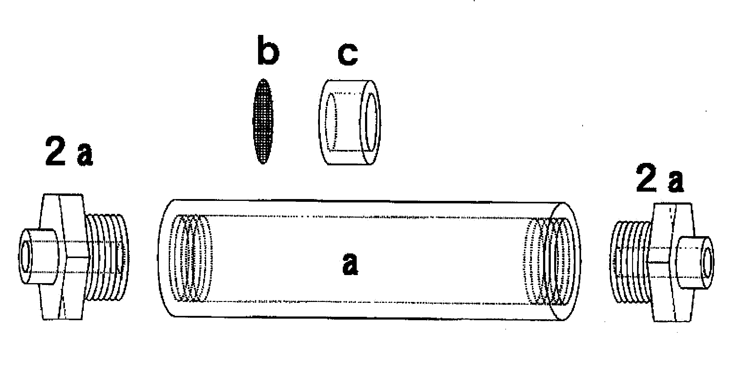
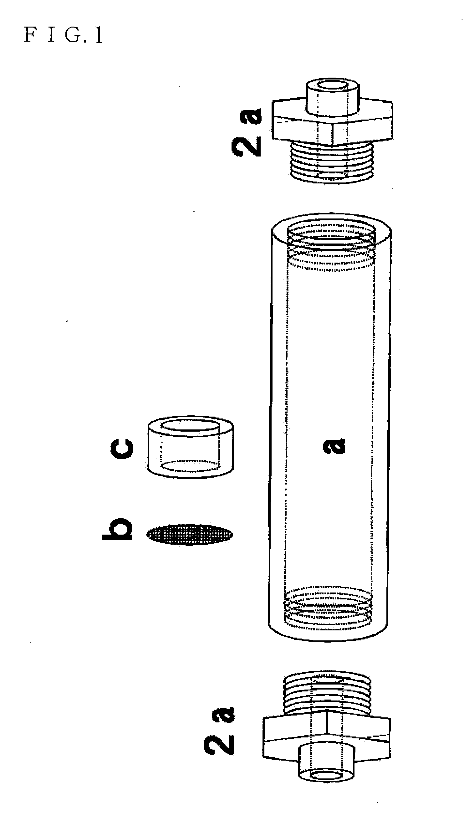
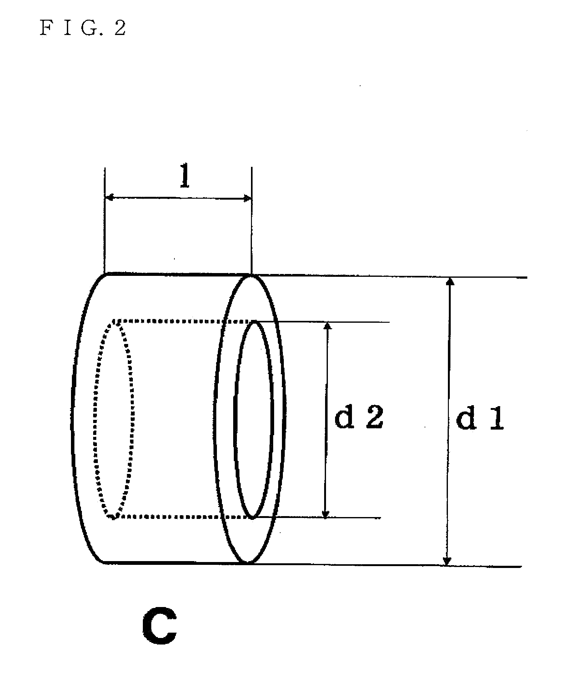
[0073]An emulsification apparatus was produced by inserting, into a cylindrical casing having an inner diameter of 20 mm, 10 units each composed of a gauze including a main gauze of 1400 mesh and a spacer having a length of 10 mm and an inner diameter of 15 mm. The length of the casing was about 120 mm.

[0074]Naphtesol being a hydrocarbon-based solvent (product of NIPPON OIL CORPORATION) and an aqueous solution of a dispersing agent (1 percent by mass of PVA205, product of KURARAY Co., Ltd.) were used as the raw materials for emulsification. The raw materials were introduced into the emulsification apparatus at flow rates of 100 ml / min and 200 ml / min using separate plunger pumps to obtain an O-W type emulsion. The volume average diameter of the liquid droplets of the dispersed phase of the emulsion (hereinafter referred to as a “volume average particle diameter”) and the particle diameter distribution of the liquid droplets were measured using the Coulter Counter (Multisizer II, prod...

manufacturing example 2

[0077]The same procedure as in Manufacturing Example 1 was repeated except that the number of the units in the casing was 40, whereby an emulsion was manufactured. The volume average particle diameter of the dispersed phase was 18 μm, and the CV value was 24%.

manufacturing example 3

[0078]The same procedure as in Manufacturing Example 1 was repeated except that a main gauze with 250 mesh was used, whereby an emulsion was manufactured. The volume average particle diameter of the dispersed phase was 55 μm, and the CV value was 25%.


PUM

PropertyMeasurementUnit
particle diameter distributionaaaaaaaaaa
particle diameteraaaaaaaaaa
linear velocityaaaaaaaaaa

Abstract

A method for controlling a particle diameter and a particle diameter distribution of emulsion particles during manufacturing of an emulsion dispersion is provided. The method includes causing two or more types of liquids substantially immiscible with each other to continuously and sequentially pass through net bodies. The net bodies are disposed in a cylindrical flow passage at intervals of 5 to 200 mm, and the number of the net bodies is more than 50 and 200 or less. Each of the net bodies is equivalent to a gauze having a mesh number of 35 mesh to 4000 mesh in accordance with an ASTM standard and has a surface that intersects the direction of the flow passage. An emulsification apparatus used for the method includes a feed pump for feeding two or more types of liquids substantially immiscible with each other; and a cylindrical flow passage to which the two or more types of liquids fed by the feed pump are delivered. A predetermined number of net bodies are disposed in the cylindrical flow passage at predetermined intervals, and each net body has a surface intersecting the direction of the flow passage.

Description

TECHNICAL FIELD[0001]The present invention relates to a method and an apparatus for controlling the particle diameter and particle diameter distribution of fine particles of a hydrophobic material in an emulsion dispersed in the form of fine particles in a dispersion medium and, more particularly, to an emulsification method and an emulsification apparatus for mass-producing a uniform emulsion having a narrow particle diameter distribution of fine particles in a continuous and stable manner. The invention also relates to a microcapsule and polymer fine particles prepared using the emulsion produced using the above method and apparatus.BACKGROUND ART[0002]An emulsion includes a continuous liquid phase and a liquid-phase material that is immiscible with the continuous phase and dispersed therein as particles. Examples of well-known emulsions include O-W type emulsions in which oil droplets are dispersed in a water-based continuous phase and W-O type emulsions in which, in contrast to ...

Claims


Application Information

Patent Timeline
Patent Type & Authority Applications(United States)
IPC IPC(8): C08F120/18B32B1/00B01J13/06B05C11/02
CPCB01F3/0807B01F5/0682B01F5/0693Y10T428/2984B01F13/1016B01J13/16C08F2/22B01F13/1013B01F23/41B01F25/45B01F25/4523B01F33/81B01F33/811
Inventor SHOKO, TOSHIKATSUHAYASHI, SHOZOHAYASHI, HIDEKOTOGAMI, YASUOTAKAGI, AKIRA
Owner NIPPON OIL CORP
Why Eureka
Try Eureka