
Electron Cyclotron Ion Source and Manufacturing Method Thereof

Inactive Publication Date: 2011-06-16
KOREA BASIC SCI INST
View PDF6 Cites 18 Cited by
  • Summary
  • Abstract
  • Description
  • Claims
  • Application Information

AI Technical Summary

Benefits of technology

[0011]The apparatus of an electron cyclotron resonance ion source according to the present invention is compact and minimizes electromagnet material consumption since the magnet is configured to have a minimized, arbitrary cross-sectional shape according to the required magnetic field gradient, instead of being configured with coils.
[0012]Further, an economical apparatus of an electron cyclotron resonance ion source providing strong magnetic field may be implemented by employing a solenoid magnet or a Bitter magnet having minimized, arbitrary cross-sectional shape for configuration of a power source alone or in combination.
[0013]In addition, a variety of apparatuses of an electron cyclotron resonance ion source may be provided considering market needs and limitation of installation space, and the cost of manufacturing a number of same apparatuses can be minimized.
[0014]Furthermore, an apparatus of an electron cyclotron resonance ion source is capable of supplying ions using an electromagnet or a superconducting magnet configured to have a cross-sectional shape optimized for magnetic fields required for X-ray analysis, material etching, particle accelerator, or the like.

Problems solved by technology

In addition, studies are being carried out about X-ray ion source as a safe, compact, inexpensive and, in particular, portable ion source, although further efforts are necessary for beam integration and guiding since the image resolution is not enough and the emission area is large.
This inevitably increases the apparatus size and becomes a hindrance to increasing the ionization area.
However, since it requires an additional device to keep cryogenic temperatures, portability and maintenance cost problems remain.
However, its application is restricted because of the use of the expensive superconducting wire.

Method used


Image

  • Electron Cyclotron Ion Source and Manufacturing Method Thereof
  • Electron Cyclotron Ion Source and Manufacturing Method Thereof
  • Electron Cyclotron Ion Source and Manufacturing Method Thereof

Examples


Embodiment Construction

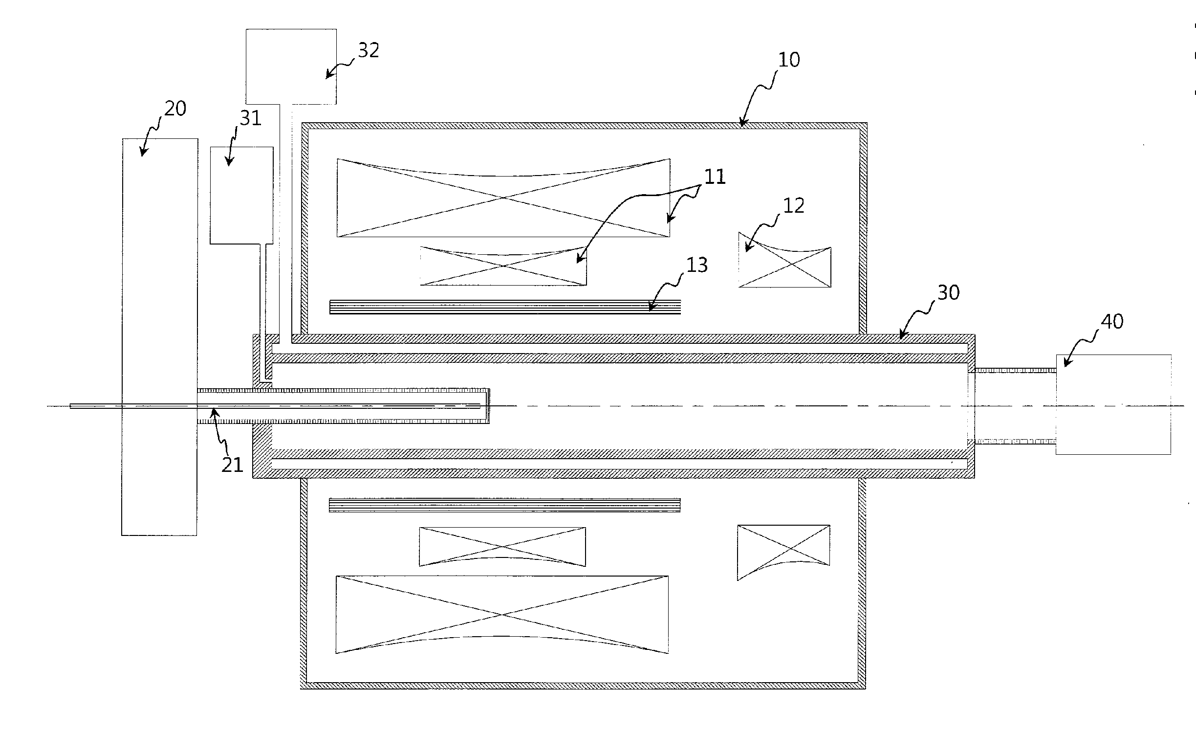
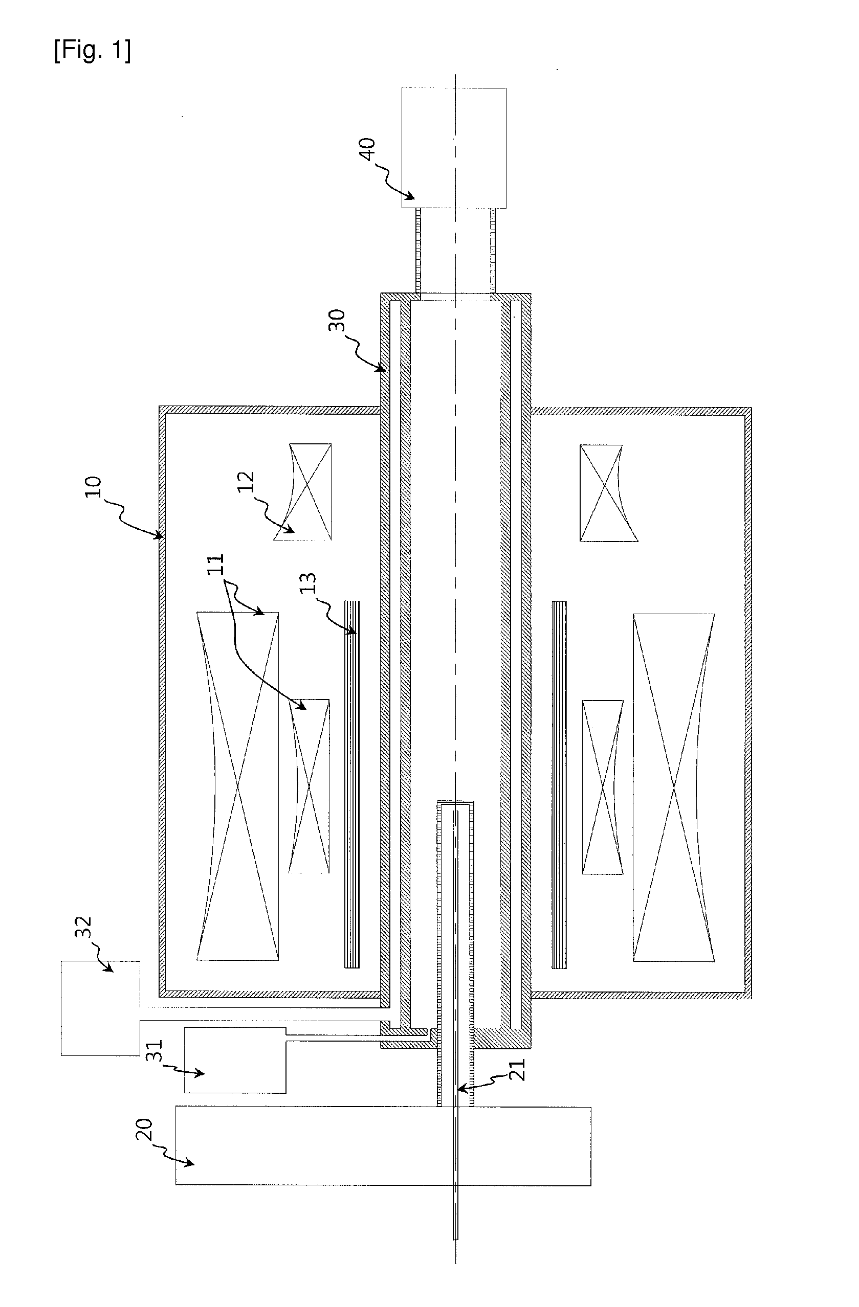
[0018]Exemplary embodiments now will be described more fully hereinafter with reference to the accompanying drawings, in which exemplary embodiments are shown. The present disclosure may, however, be embodied in many different forms and should not be construed as limited to the exemplary embodiments set forth therein. Rather, these exemplary embodiments are provided so that the present disclosure will be thorough and complete, and will fully convey the scope of the present invention to those skilled in the art.

[0019]Now, an apparatus of an electron cyclotron resonance ion source according to an embodiment of the present invention will be described in detail referring to the attached drawings.

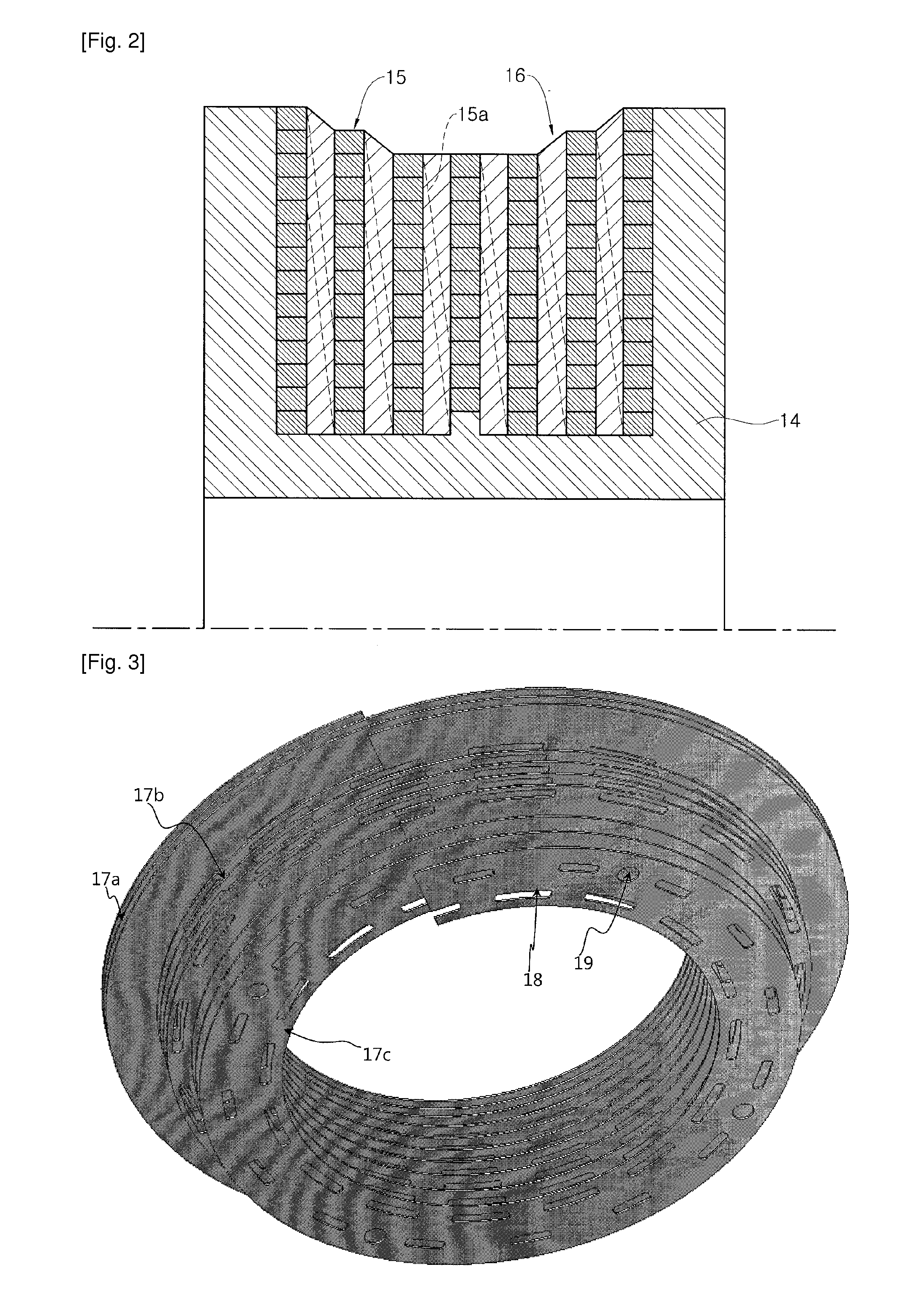
[0020]FIG. 1 schematically illustrates an apparatus of an electron cyclotron resonance ion source according to an embodiment of the present invention, FIG. 2 is a schematic diagram showing a magnet unit of an apparatus of an electron cyclotron resonance ion source according to an embodiment of t...


PUM


Abstract

An apparatus of an electron cyclotron resonance ion source may include: a magnet unit containing a magnet for generating magnetic fields; an ionizing chamber housing unit for generating ions through electron cyclotron resonance from a plasma; a microwave generating unit for injecting microwaves to the ionizing chamber housing unit to generate ions; and a beam integrating and guiding unit for treating the generated ions. The magnet unit may include: a bobbin for winding the magnet; a variable spacer for dividing the bobbin into a plurality of sections; and the magnet which is wound into the form of a wire or a tape in the plurality of sections formed by the variable spacer.

Description

TECHNICAL FIELD[0001]An aspect of the present invention relates to an apparatus of an electron cyclotron resonance ion source and a manufacturing method thereof, specifically to an electromagnet or a superconducting magnet capable of varying cross-sectional shape for generation of magnetic fields. More particularly, it relates to an apparatus of an electron cyclotron resonance ion source capable of supplying ions for X-ray analysis, material etching, particle accelerators, or the like by providing an electromagnet or a superconducting magnet with a cross-sectional shape optimized for the required magnetic field and a manufacturing method thereof.BACKGROUND ART[0002]Generally, a variety of electron cyclotron resonance ion sources are used in many applications because ions can be generated at relatively low cost. The electron cyclotron resonance ion sources are used in various forms in many applications.[0003]For example, there have been several successful proposals for large-area ion...

Claims


Application Information

Patent Timeline
IPC IPC(8): H05H13/02H01J9/24
CPCH01J27/18H01J37/08H01F2005/022H01F7/202H01F41/0687H01J2237/0817H01F41/098H01J37/317
Inventor WON, MI-SOOKLEE, BYOUNG-SEOBKIM, JONG-PILYOON, JANG-HEEBAE, JONG SEONGBANG, JEONG KYULEE, HYOSANGPARK, JINYONG
Owner KOREA BASIC SCI INST
Learn More