Middle ear implant and method

a technology of middle ear and implant, which is applied in the field of middle ear implants, can solve the problems of insufficient stimulation of cochlea and/or auditory nerve, inability to transmit sound into the outer ear canal, and inability to align the magnetic field with the magnetic field, so as to reduce the number or types of tools required, and the effect of shortening the procedure duration

Inactive Publication Date: 2011-06-16
OTOTRONIX
View PDF10 Cites 48 Cited by
  • Summary
  • Abstract
  • Description
  • Claims
  • Application Information

AI Technical Summary

Benefits of technology

[0025]The primary advantages of a shape memory material include that it can be formed into a desired shape without permanently deforming the material. The material can be returned to its original shape by applying heat and without the use of mechanical force (e.g. crimping tool). If the material is inadvertently deformed into an undesired shape, it can be returned to its original shape by applying heat. The transition temperature set point can be established at a desired value by modifying the alloy composition and / or by heat treatment.
[0026]Above this transition set point the material has superelastic properties, and below this point the material has more plastic properties. “Superelastic”, or “very springy” properties may have advantages in certain applications where it is desirable for the material to return to the original shape after experiencing force; plastic properties may have advantages in certain applications where it is desirable for the material to conform to a new shape after experiencing force.
[0027]Other potential benefits of using shape memory material are that it reduces the number or types of tools required to conduct a surgical procedure. It provides for shorter duration of the procedure, and allows for access into smaller or obscured areas.

Problems solved by technology

In general, however, sound entering the outer ear canal does not get transmitted to the inner ear and / or transmitted to the auditory nerve.
When something is defective in this ossicular chain, however, such transmission does not occur sufficiently to stimulate the cochlea and / or the auditory nerve.
Regardless of the particular implant or mounting technique used for a middle ear magnet, problems can arise with regard to alignment of the magnetic with the magnetic field.
However, the nature of the ECE transducer is such that the power delivered by the coil to the magnet is sensitive to the coil-magnet alignment.
If the implanted magnet is not optimally aligned with the external coil from which the electromagnetic signal propagates, the implanted magnet might not respond adequately.
Thus, a magnet that has been rigidly clamped to the incudostapedial joint of the ossicular chain will not necessarily be at the optimum alignment to the ear canal and can be misaligned.
A disadvantage of clip mechanisms known in the prior art is difficulty in aligning the magnet with different patient anatomies.
If the magnet is at an angle to the coil, energy transfer efficiency will be lost.
Therefore, if a magnet is clipped onto the stapes, which is itself at an angle to the ear canal, then the coil and magnet will not be properly aligned, and energy transfer to the magnet and, consequently, the ossicular chain and cochlea, will be diminished
Clamping or clipping onto living bone (ossicles) can also compromise oxygen and nutrient delivery, thus resulting in necrosis of the ossicles.
However, this can result in a loose fit, and if the magnet is allowed to vibrate loosely about the ossicle, this will result in loss of performance and a “rattling” effect for the patient.
Another disadvantage of this type of mechanism is that the tissue formation required to create contact between the coils and ossicles takes several weeks to form after surgery.
As a result, the orientation of the magnet may move during the healing time, and can become permanently misaligned once the tissue forms.
It is not desirable to do this as the ossicular chain is quite delicate and a mishap could result in additional or total hearing loss.
For example, known support structures, such as GELFOAM™, which is used to hold a magnet in position during the healing process, may become dislodged and allow the magnet to move; tissue growth may occur non-uniformly between the magnet and the ossicle, thus altering the initial position of the magnet; and forceful physical activities may move the magnet out of position prior to tissue fully encapsulating it.

Method used


Image

  • Middle ear implant and method
  • Middle ear implant and method
  • Middle ear implant and method

Examples


Embodiment Construction

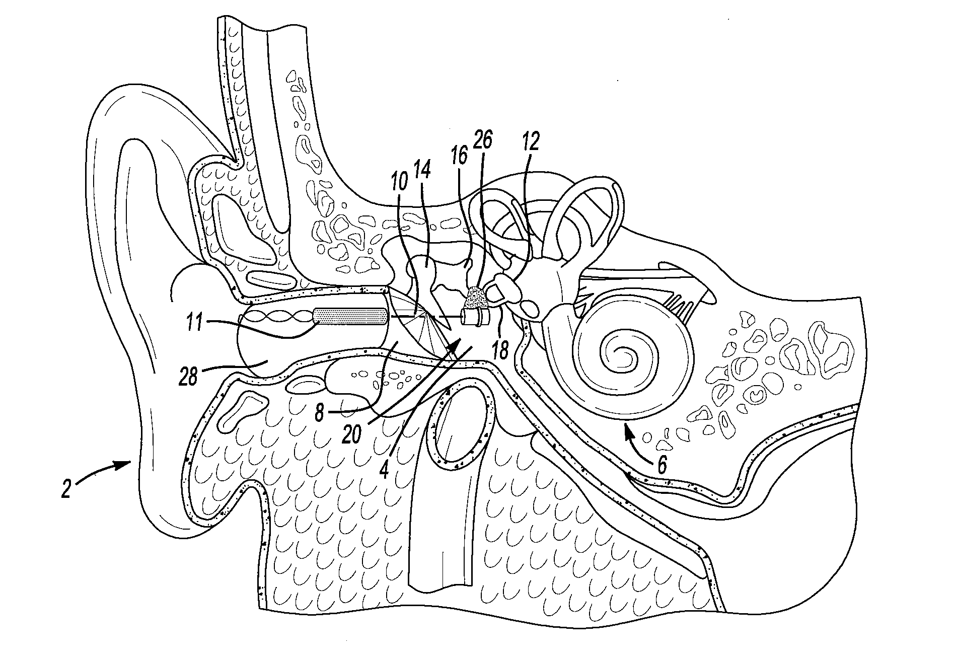
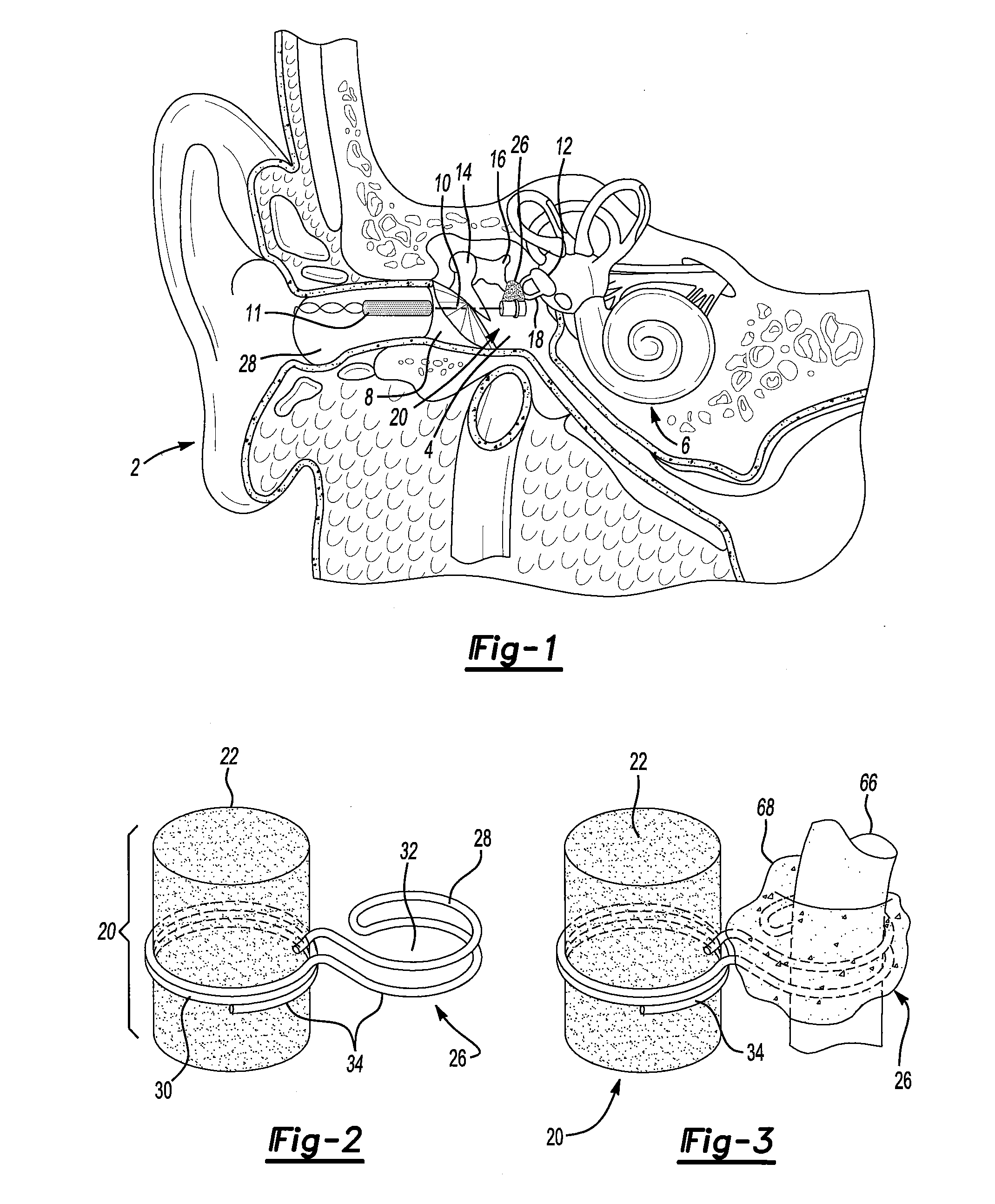
[0048]A human ear is represented in FIG. 1. It includes an outer ear 2, a middle ear 4, and an inner ear 6. Pertinent to the description of the present invention is an outer ear canal 8 which is normally closed at its inner end by tympanic membrane, or eardrum, 10. Also pertinent is an ossicular chain, which, if intact, extends from tympanic membrane 10 to oval window 12 defining an entrance to the inner ear 6. The intact ossicular chain extends through the middle ear 4 and includes a malleus 14, an incus 16, and a stapes 18. A properly functioning ossicular chain transmits vibrations from the tympanic membrane 10 in series through the malleus 14, the incus 16 and the stapes 18 to the oval window 12. Vibrations at the oval window stimulate the inner ear 6, whereby the person perceives the sound received in the outer ear 2.

[0049]An object of the present invention is to provide the vibratory stimulation to the inner ear 6 when there otherwise is inadequate vibration transmission in th...


PUM


Abstract

An improved middle ear implant and method are disclosed. The invention particularly relates to magnetic implants and to attachment devices and methods for mounting a magnet in the middle ear of a patient. The implant comprises a wire-form and a magnet disposed in a housing. The method may comprise the steps of: positioning a magnet in optimal alignment; and attaching said magnet to an ossicle in the middle ear. The method may further comprise the step of using a wire-form to attach the implant to the ossicle. Still further, the method may comprise the step of anchoring the implant to the ossicle with biological cement.

Description

[0001]This application claims the benefit of U.S. provisional patent application No. 61 / 247,742, filed on Oct. 1, 2009. The contents of this provisional application are fully incorporated herein by reference.FIELD OF THE INVENTION[0002]The present invention relates generally to the field of middle ear implants and improvements in obtaining sound quality for middle ear implant patients. The invention more particularly relates to improved apparatus and methods used in, or with, magnetic middle ear hearing systems. The present invention most particularly relates to improved magnetic implants and to improved attachment devices and methods for mounting a magnet in the middle ear of a patient.BACKGROUND OF THE PRESENT INVENTION[0003]There are many different reasons why some people have hearing impairment. In general, however, sound entering the outer ear canal does not get transmitted to the inner ear and / or transmitted to the auditory nerve. In some instances, this can be solved by ampli...

Claims


Application Information

Patent Timeline
Patent Type & Authority Applications(United States)
IPC IPC(8): H04R25/00
CPCH04R2225/67H04R25/606
Inventor SPEARMAN, MICHAEL R.SPEARMAN, BRIAN M.HOLLNAGEL, ERIC M.KRAUS, ERIC M.
Owner OTOTRONIX
Why Eureka
Try Eureka