Centrifugal reverse flow disk turbine and method to obtain rotational power thereby

a centrifugal reverse flow and disk turbine technology, applied in the direction of machines/engines, stators, liquid fuel engines, etc., can solve the problems of urban environment in mega-cities like tokyo that is still getting worse and worse, urban warming (or heat island), and down-sized prime mover. , to achieve the effect of low steam rate, high cost performance and high thermal efficiency

Active Publication Date: 2011-07-07
SAITOH TAKEO S
View PDF3 Cites 36 Cited by
  • Summary
  • Abstract
  • Description
  • Claims
  • Application Information

AI Technical Summary

Benefits of technology

[0050]Another object of the invention is to provide an improved down-sized centrifugal reverse flow disk turbine having a low steam rate and a high therm

Problems solved by technology

While, urban environment in mega-cities like Tokyo is still getting worse and worse.
This serious environmental issue is called “urban warming (or heat island)”, which is caused by a concentrated consumption of energy in the urban area.
However, the renewable energy is dispersed and attainable temperature and pressure are sometimes low, thereby leading to a down-sized prime mover.
Further, multi-staging and reheating/regenerating cycles, which have been very common in conventional large-steam turbines could not be exploited in a small turbine because of a strict cost limitation.
This causes complicatedness and high cost of a entire system (about 100˜500 times higher than conventional gasoline engine and the same power rated engines).
This fact greatly hinders market permeation of the small-sized turbines.
Nonetheless, the thermal efficiency of even the latest most advanced fossil-powered steam turbine is at most 40˜42%, this value being only 60% of the ideal Carnot cycle efficiency.
However, mankind is now facing an unprecedented environmental age; namely, global warming due to CO2 emissions, urban warming due to heat emissions in city area, exhaustion of fossil and nuclear fuels, problems of population growth, food production, drinking water scarcity, and other resources.
Advanced technologies such as multi-staging and reheating/regenerating cycles, which have been very common in conventional large-steam turbines, could not be exploited anymore in a small turbine because of a strict cost limitation.
Although its reliability and cost effectiveness are overwhelming, efforts toward an improvement of the thermal efficiency of the gasoline engine is strictly limited owing to an old cycle of the engine, i.e. the Otto cycle.
This engine could not survive any more in the environment-c

Method used


Image

  • Centrifugal reverse flow disk turbine and method to obtain rotational power thereby
  • Centrifugal reverse flow disk turbine and method to obtain rotational power thereby
  • Centrifugal reverse flow disk turbine and method to obtain rotational power thereby

Examples


first embodiment

the Present Invention

[0145]Said disk rotor 1 in the first embodiment is comprised of a spacer disk 20 shown in FIG. 3A, and a rib-shaped blade disk with flow channels, shown in FIG. 3B, and two kinds of disks are laminated by turns in the axial direction to make a disk rotor. The spacer disk has buckets (cusps) at peripheral and axial mouths placed near said rotor shaft. The blade disk has a plurality of rib-shaped blades 25 and small buckets 22 with the same shape as the one in spacer disk 20.

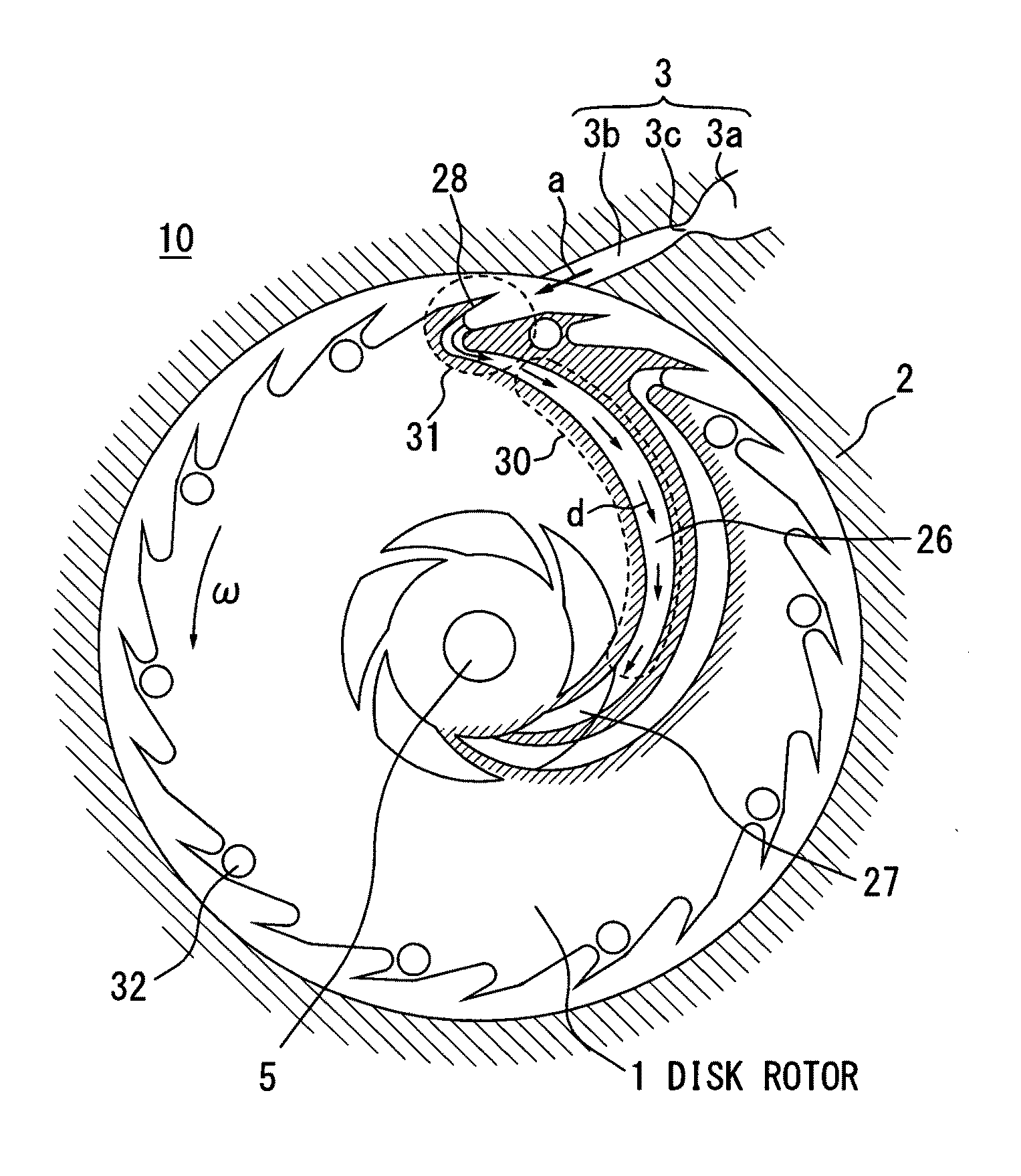
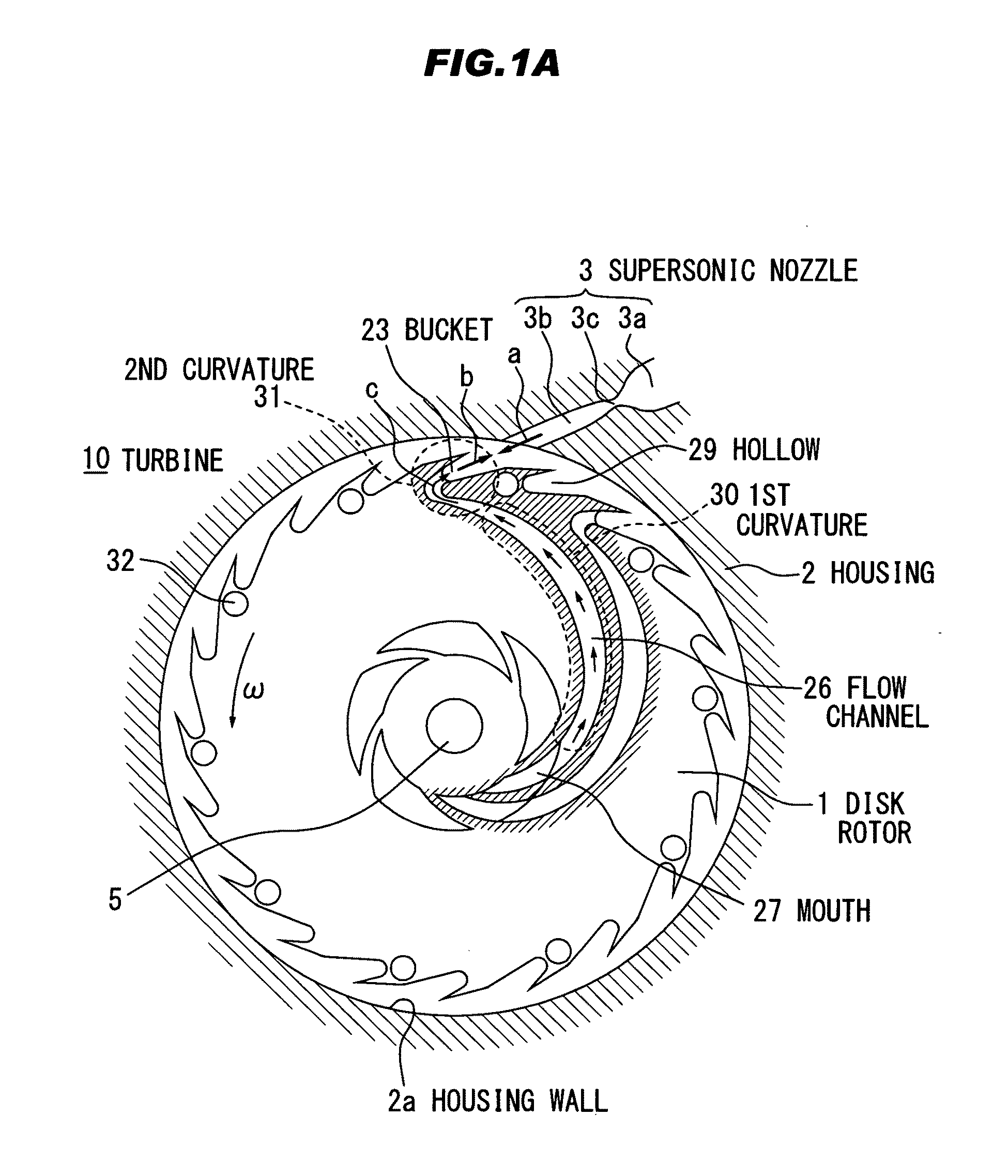
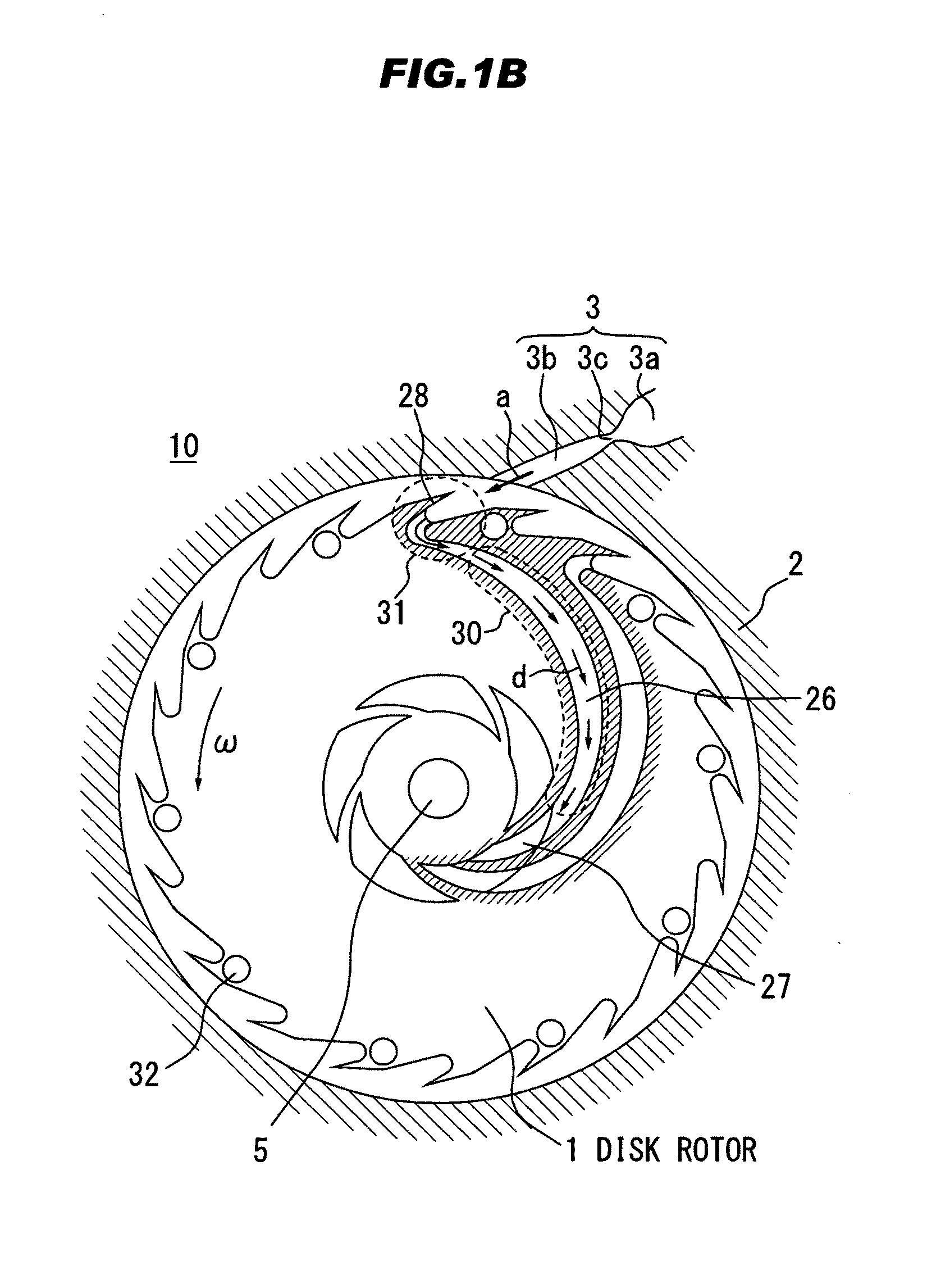
[0146]As shown in FIG. 3C, by laminating the blade disk and the spacer disk together in the axial direction, the radial flow channel 26 is formed in between two disks. This flow channel has two curvatures; one is located on the way to the second curvature and has a large radius of curvature with a concaved shape to rotational direction, another is located near the tip and having a small radius curvature with a convexed shape to rotational direction.

[0147]Axial suction mouths are placed near sa...

second embodiment

the Present Invention

[0169]The second mode for carrying out the invention is a united or integrated structure including said two spacer disks and one blade disk. This structure is quite different from that of the first mode for carrying out the invention, in which a plurality of spacer and blade disks are alternatively laminated. An entire rotor is combinedly formed by piling up in the axial direction.

[0170]The said disk rotor 1 also has a plurality of radial flow channels 26 and the united blade and spacer disks are laminated in the axial direction. Aforementioned axial suction mouth can take an arbitrary shape, but it is desirable that the total aperture area should be by far larger than the total inlet area of the radial flow channels.

[0171]Said disk rotor 1 is comprised of lamination of a united hub-and-spoke shaped blade and spacer disk with flow channels having two curvatures, radially directed, and axial suction mouths placed near said rotor shaft and united blade and spacer ...


PUM


Abstract

A centrifugal reverse flow disk turbine for power generation, comprising; a) a turbine shaft; b) a disk rotor disposed on said turbine shaft; c) a housing, having said turbine shaft and said disk rotor, bearings, seal devices, and at least one jet nozzle means; d) a plurality of radially engraved channel for transporting working fluid from entering ports, placed axially near said turbine shaft; e) a plurality of said channels having two curvatures; first curvature has a small radius, and concaved pertinent to rotational direction of said rotor, starting from the entering port to middle of its flow path, and the second curvature has a large radius, convexed pertinent to rotational direction of said rotor, positioned near the peripheral of said rotor; a plurality of a buket attached at every flow channel, directing against nozzle disposed on said housing, thereby deriving impinging counter supersonic flow.

Description

BACKGROUND OF THE INVENTION[0001]1. Field of the Invention[0002]This invention in general relates to a prime mover based upon a centrifugal reverse flow disk turbine, which is applicable to steam, gas, water, and air turbines, and a method to yield a rotational power thereby.[0003]2. Related Art[0004]In conventional turbines, which have been operated in fossil and nuclear power plants, for example, large-scale steam (water) turbines more than one gigawatt (GW) under a supercritical condition are utilized in order to minimize the steam rate and to improve the thermal efficiency thereof.[0005]However, it is estimated that these fossil and nuclear fuels on the earth would run out at end of this century as clearly projected in FIG. 11. FIG. 11 includes all kind of energy resources on the earth, i.e. fossil fuels (oil, coal, and natural gas), and nuclear fuel, as well as methane hydrate therewith.[0006]Another crucial issue human beings are now facing with is global warming due to carbon...

Claims


Application Information

Patent Timeline
IPC IPC(8): F01D1/06F01D5/14F03B3/00F03D5/00F04D29/44
CPCF01D1/026F01D1/32F01D1/36F05D2250/713Y02E10/34F05D2200/23F01D5/028Y02E10/30
Inventor SAITOH, TAKEO S.
Owner SAITOH TAKEO S
Why Eureka
Try Eureka