Process for producing paraffinic hydrocarbons

a technology of paraffinic hydrocarbons and hydrocarbons, which is applied in the direction of hydrocarbon oil treatment products, physical/chemical process catalysts, metal/metal-oxide/metal-hydroxide catalysts, etc. it can solve the problems of undesirable cold flow properties of straight chain paraffins and mainly normal alkanes, and achieve excellent cold flow properties and optimise the stability of hydro-isomerisation catalysts.

Active Publication Date: 2011-07-07
SHELL USA INC
View PDF6 Cites 6 Cited by
  • Summary
  • Abstract
  • Description
  • Claims
  • Application Information

AI Technical Summary

Benefits of technology

[0008]It has now been found that a feedstock containing triglyceride, diglycerides, monoglycerides and / or fatty acids can be converted into paraffinic diesel components with excellent cold flow properties by applying a hydro-deoxygenation / hydro-isomerisation process wherein a hydroprocessing catalyst comprising sulphided Ni and sulphided W or Mo as hydrogenating components on an acidic catalyst carrier is used in the hydro-isomerisation step. By using a catalyst comprising sulphided Ni and sulphided W or Mo as hydrogenating components in the hydro-isomerisation step instead of a catalyst using a noble metal hydrogenating component, there is no need to completely remove impurities such as hydrogen sulphide, ammonia and water from the effluent of the hydro-deoxygenation step before it is contacted with the hydro-isomerisation catalyst. Removal of the greater part of the water appears to be sufficient for optimising the stability of the hydro-isomerisation catalyst.

Problems solved by technology

In the process of U.S. Pat. No. 4,992,605, straight chain paraffins are produced that have undesirable cold flow properties, i.e. a relatively high pour point and cloud point.
Also in the process of U.S. Pat. No. 5,705,722, mainly normal alkanes are produced that have undesirable cold flow properties, i.e. a relatively high pour point and cloud point.

Method used


Image

  • Process for producing paraffinic hydrocarbons

Examples


example

[0048]The invention will be further illustrated by means of the following non-limiting example.

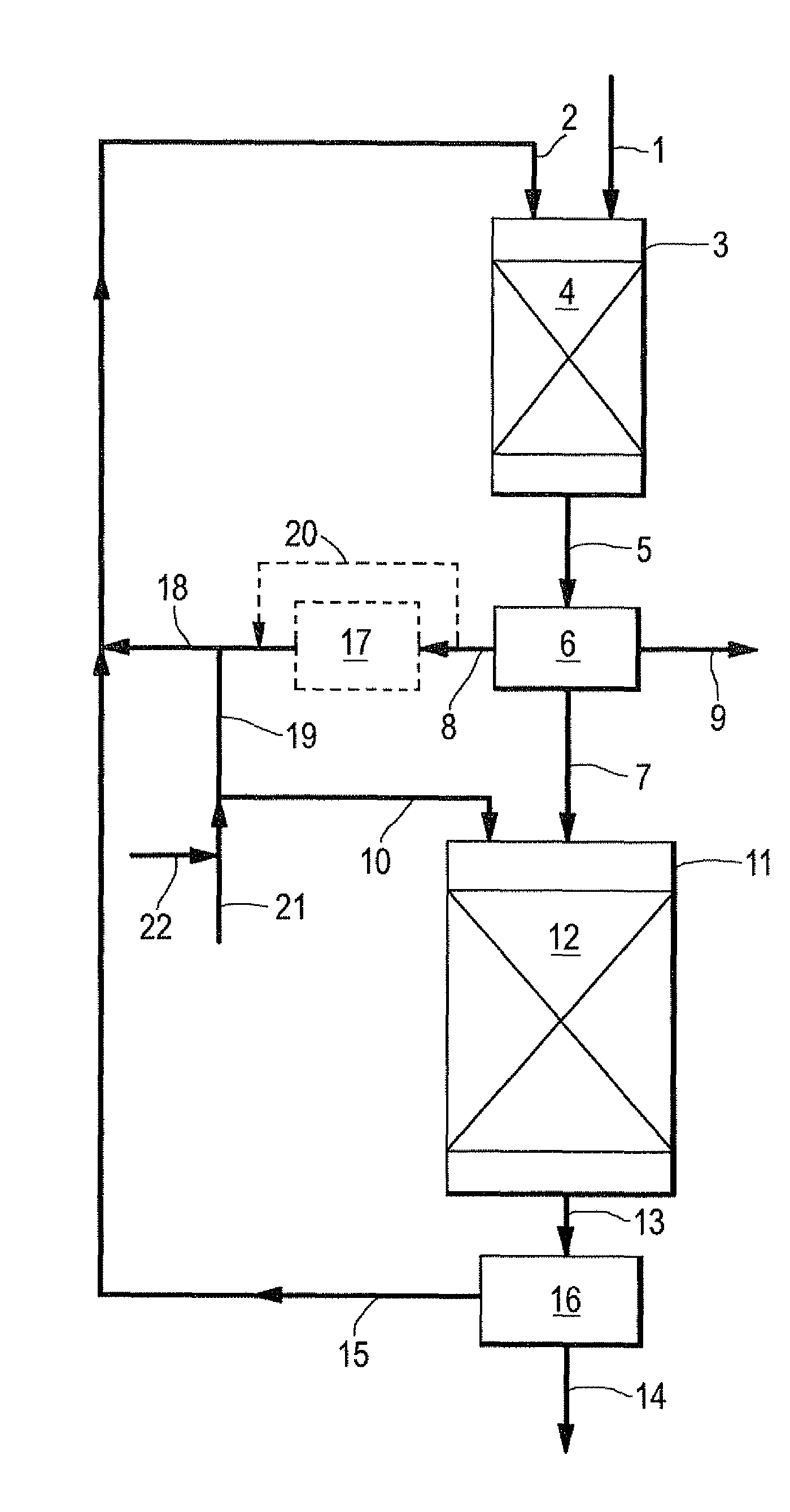
[0049]Refined palm oil was, in a first reactor, hydrodeoxygenated over a bed of sulphided hydrogenation catalyst. The effluent of the first reactor was separated into a liquid stream rich in paraffinic hydrocarbons and a gaseous stream in a high temperature, high pressure separator. The liquid stream rich in paraffinic hydrocarbons had a water content of 20 mg / kg (20 ppmw) and was fed at a weight hourly space velocity of 1.0 kg oil per litre catalyst per hour to a second reactor containing a catalyst bed with 75 mL hydro-isomerisation catalyst (5 wt % NiO and 21 wt % W2O3 on amorphous silica-alumina) and 75 mL silicon carbide spheres. A stream of pure hydrogen was supplied to the second reactor at a rate of 1,500 NL hydrogen per kg liquid stream. In order to keep the hydro-isomerisation catalyst in sulphided form, di-tert-butyl polysulphide in an amount equivalent to 5000 ppm sulphur based...


PUM

PropertyMeasurementUnit
pressureaaaaaaaaaa
temperatureaaaaaaaaaa
total pressureaaaaaaaaaa

Abstract

A process for producing paraffinic hydrocarbons from a feedstock comprising triglycerides, diglycerides, monoglycerides and/or fatty acids, the process comprising the following steps: (a) hydrode oxygenating the triglycerides, diglycerides, monoglycerides and/or fatty acids in the feedstock by contacting hydrogen and the feedstock with a hydrogenation catalyst at a temperature in the range of from 250 to 380° C. and a total pressure in the range of from 20 to 160 bar (absolute), to obtain an effluent comprising paraffinic hydrocarbons and water; (b) separating a liquid stream rich in paraffinic hydrocarbons from the effluent obtained in step (a); and (c) hydroisomerising the paraffinic hydrocarbons in the liquid stream rich in paraffinic hydrocarbons by contacting hydrogen and the liquid stream with a hydroprocessing catalyst comprising sulphided Ni and sulphided W or Mo as hydrogenation components on a carrier comprising amorphous silica-alumina and/or a zeolitic compound at a temperature in the range of from 280 to 450° C. and a total pressure in the range of from 20 to 160 bar (absolute).

Description

FIELD OF THE INVENTION[0001]The invention provides a process for producing paraffinic hydrocarbons from a feedstock comprising triglycerides, diglycerides, monoglycerides and / or fatty acids, in particular from vegetable oil, animal fat or fish oil.BACKGROUND OF THE INVENTION[0002]It is known that paraffinic hydrocarbons boiling in the diesel range may be produced from triglyceride-comprising feedstocks from biological origin such as vegetable oil, animal fat or fish oil.[0003]In U.S. Pat. No. 4,992,605 for example is disclosed a process for producing hydrocarbon products in the diesel boiling range, mainly C15-C18 straight chain paraffins. The process comprises hydroprocessing vegetable oils or some fatty acids at conditions effective to cause hydrogenation, hydrotreating and hydrocracking of the feedstock (temperature 350-450° C.; pressure 4.8-15.2 MPa; liquid hourly space velocity 0.5-5.0 hr−1) using a commercially available hydroprocessing catalyst. Cobalt-molybdenum and nickel-m...

Claims


Application Information

Patent Timeline
Patent Type & Authority Applications(United States)
IPC IPC(8): C07C1/207
CPCB01J21/12B01J23/883B01J23/888C10G2400/04B01J37/20C10G45/02C10G2300/1011B01J29/06Y02P30/20
Inventor VAN BEIJNUM, JOHANNESCREYGHTON, EDWARD JULIUSJANSSEN, ANDRIES HENDRIK
Owner SHELL USA INC
Why Eureka
Try Eureka