Method for manufacturing carbonaceous film, and graphite film obtained thereby

a technology of graphite film and carbonaceous film, which is applied in the direction of carbon preparation/purification, inorganic chemistry, carbon compounds, etc., can solve the problems of inability to achieve advantageous high thermal conductivity, difficulty in allowing polymer graphite film to have a still larger area, etc., and achieves favorable thermal conductivity, high quality, and large area

Active Publication Date: 2011-07-14
KANEKA CORP
View PDF6 Cites 10 Cited by
  • Summary
  • Abstract
  • Description
  • Claims
  • Application Information

AI Technical Summary

Benefits of technology

[0050]According to the present invention, fusion of material films with each other in the carbonization step is prevented, and thus obtaining a long carbonaceous film having a large area with favorable productivity is enabled. The obtained carbonaceous film can be easily converted into a high quality graphite film using a known technique. By using the method of the present invention, a long graphite film having a large area, which has been difficult to produce, can be easily produced.
[0051]In addition, the aforementioned Patent Document 4 (JP-A No H5-132360) discloses that obtaining a graphite film having a length not shorter than the cylindrical circumference is difficult unless other film is used as a separator; however, the production method of the present invention enables a long graphite film having a large area to be easily produced. It should be noted that the aforementioned Patent Document 3 (JP-A No. S63-256508) discloses to sandwich a polymer film between two bodies of cylindrical graphitous carbon, but the construction and effects of the constraining means according to the present invention have not been suggested.

Problems solved by technology

However, allowing polymer graphite films to have a still larger area is difficult, and thus use thereof has been limited to a part of small equipments, etc., irrespective of their superior performances.
Since thus joined part has a large heat resistance, failure in achieving advantageous high thermal conductivity occurs, and significant disadvantages also in light of the production costs have resulted.
According to a method for obtaining a graphite film by baking a sheet type material film, dimension of producible graphite is limited by inside dimension of a baking space of the furnace employed; therefore, the method has not been suitable for the goal of producing a graphite film having a large area.
However, such a method of baking carried out with a circular cylinder vessel involves the following problems.
As described above, in order to obtain a graphite film by baking the polymer film, the film is obliged to become a glassy carbonaceous film state having extremely inferior mechanical strength during a step of its production.
Increase in the number of times of wrapping around the core for obtaining a long graphite film results in significant problems that the film is broken concomitantly with shrinkage in the carbonization step, or that the films are fused with each other.
Once fused, such a carbonaceous film does not restore even in the following graphitization step, and as a result, a broken graphite film, or a graphite film accompanied by very wrong surface conditions may be obtained.

Method used


Image

  • Method for manufacturing  carbonaceous film, and graphite film obtained thereby
  • Method for manufacturing  carbonaceous film, and graphite film obtained thereby
  • Method for manufacturing  carbonaceous film, and graphite film obtained thereby

Examples


examples

[0118]Hereinafter, the present invention will be explained in more detail by way of Examples and Comparative Examples. It is to be noted that the flow rate of nitrogen stream in Examples and Comparative Examples indicates the flow rate of nitrogen gas at an ambient pressure, outside the electric furnace.

[0119]

[0120](Fusion)

[0121]Fusion was evaluated as: “a lot present” when fusion occurred in the entirety; “somewhat a lot present” when fusion occurred in the range of at least 20 layers; “present” when fusion occurred in the range of at least 10 layers; “a few present” when fusion occurred in the range of 5 or less layers; “slightly present” when fusion occurred in the range of 3 or less layers; “hardly present” when fusion occurred in the range of 3 or less layers, which were detachable by hand; and “absent” when no fusion occurred.

[0122](Ruffling)

[0123]As shown in FIG. 10, ruffling was evaluated as: “slightly present” when ruffling having a length of 30 mm or less and an amplitude ...

example a1

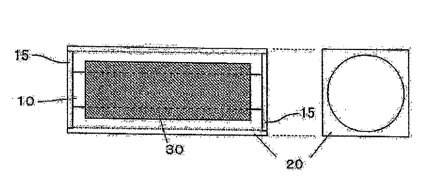
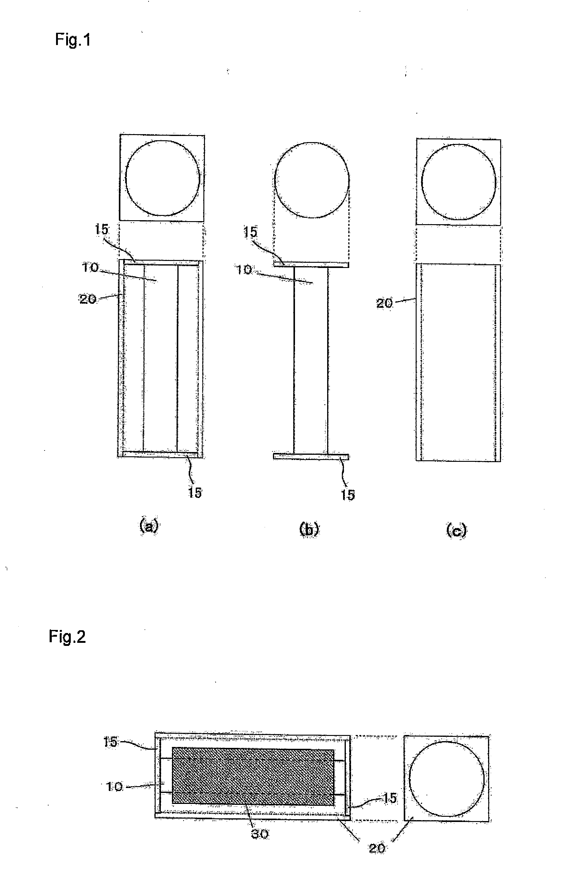
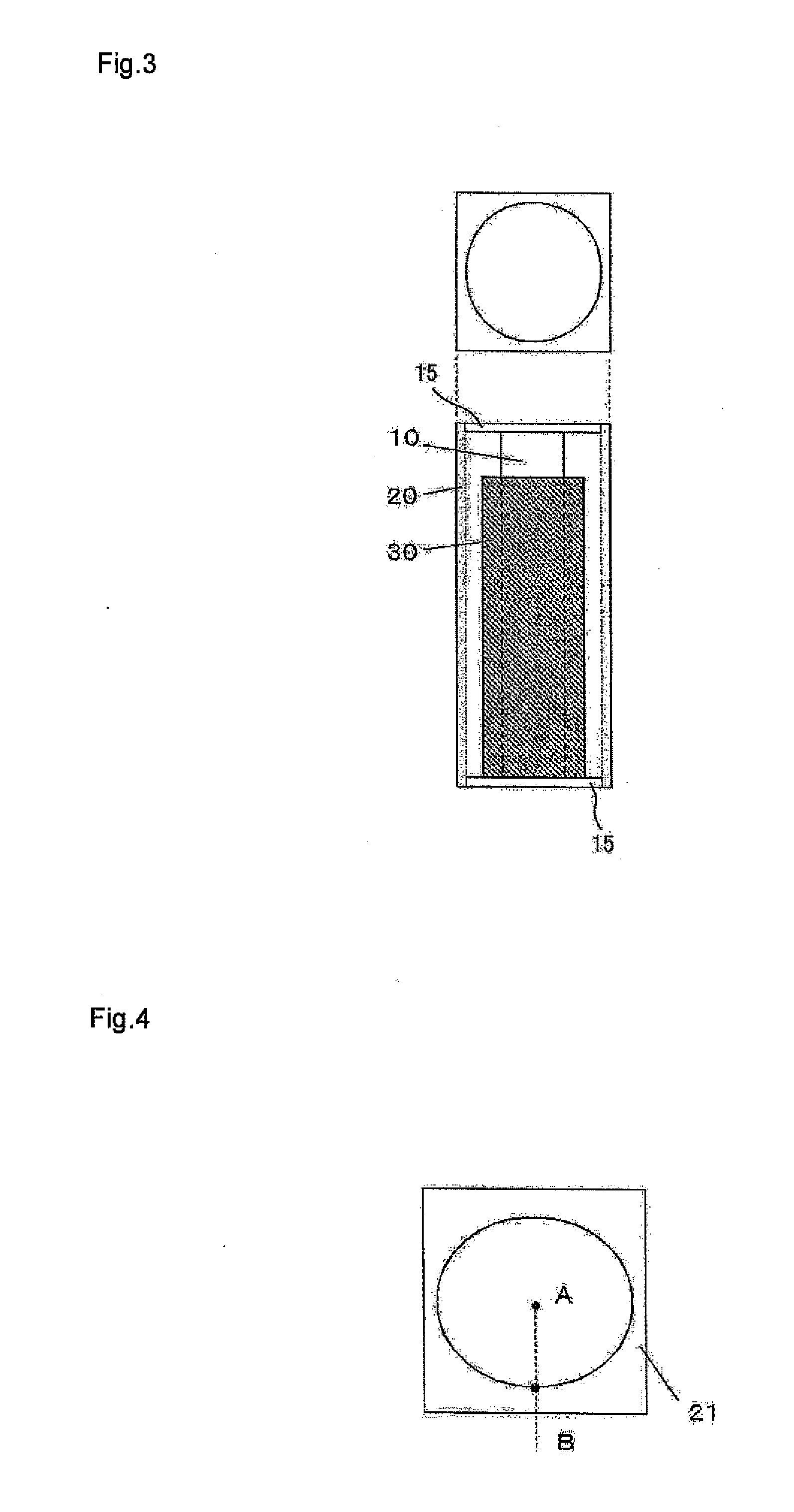
[0136]As a polymer film, a polyimide film (trade name: Apical 50AH film; thickness: 50 μm) manufactured by Kaneka Corporation, having a width of 250 mm was provided. With reference to FIG. 2, this polymer film was wrapped around a central region of the core 10 of the vessel “a” to give 50 layers, and the core 10 wrapped by the film was placed into the outer casing 20, which was further placed into inner case 55 covered with disc 15 as a lid. Thus provided vessel “a” was transversely situated in an electric furnace as shown in FIG. 8, and the temperature was elevated up to 1,000° C. at a rate of 2° C. / min by electrification and heating with heater 50 provided on the external side of the vessel to execute a carbonization treatment. In the carbonization treatment atmosphere, nitrogen was not allowed to flow, and the temperature elevation was continued while keeping the internal pressure at −0.01 kPa by reducing the pressure with a vacuum pump from pressure reduction opening 70. After c...

example a2

[0138]A carbonaceous film was produced by an entirely similar method to Example A1 using the vessel “a” except that the temperature elevation was continued in the carbonization treatment atmosphere without allowing nitrogen to flow while keeping the internal pressure at −0.1 kPa. The thickness, the surface condition, and the weight per unit area (g / m2), and the thermal diffusivity after the graphitization treatment of the carbonaceous film are summarized in Table 1. The phrase “internal pressure being −0.1 kPa with vacuum pump” herein referred to means that the internal pressure of the electric furnace is lower than the outside pressure of the electric furnace by 0.1 kPa.


PUM

PropertyMeasurementUnit
pressureaaaaaaaaaa
temperatureaaaaaaaaaa
thicknessaaaaaaaaaa

Abstract

In a method for producing a carbonaceous film in which a polymer film is wrapped around a core and is subjected to a heat treatment, material film surfaces during the carbonization step are prevented from fusion, whereby a long carbonaceous having a large area film is obtained.Fusion can be prevented by subjecting a polymer film to a heat treatment under a reduced pressure, and under a reduced pressure while allowing an inert gas to flow. The range of the pressure reduction is preferably −0.08 MPa to −0.01 kPa. It is preferred to carry out carbonization with the pressure reduced in the range of from −0.08 MPa to −0.01 kPa while allowing an inert gas to flow. In addition, the polymer film wrapped around the core is placed in an outer casing, and provided that a value derived by dividing (internal diameter of the outer casing−diameter of the core) by 2 is designated as “a” (mm), and a thickness of wrapping of the polymer film is designated as “b” (mm), a value (b / a) derived by dividing the “b” by the “a” is set to fall within the range of from 0.2 to 0.9.

Description

TECHNICAL FIELD[0001]The present invention relates to a method for producing a carbonaceous film used as a heat dissipation member in electronic instruments, precision instruments, and the like.BACKGROUND ART[0002]Graphite has been extensively used as thermal diffusion / heat dissipation materials, heat resistant sealing materials, gaskets, separators for fuel cells and the like due to having excellent heat resistance, chemical resistance, thermally conductive properties and electrically conductive properties, and low permeability of gasses. Graphite has thermal and electrical properties that greatly differ between those along the a-b plane direction and the c-axis direction. More specifically, anisotropy of the thermal conductivity in the directions along the a-b plane and the c-axis reaches 50 to 400 times. Heat dissipation films of graphite are employed for allowing thus generated heat to be diffused quickly over a large area taking advantage of such properties. Exemplary methods f...

Claims


Application Information

Patent Timeline
Patent Type & Authority Applications(United States)
IPC IPC(8): C01B31/00
CPCC01B31/02C01B31/04C01B32/05C01B32/205
Inventor INADA, TAKASHINISHIKAWA, YASUSHIMISHIRO, MAKOTO
Owner KANEKA CORP
Why Eureka
Try Eureka