Hydrogen penetration barrier

a technology of hydrogen gas and water penetration, applied in the field of hydrogen penetration barrier, can solve the problems of weakening the material configuring the container, generating very small operation noise, and difficult to handle hydrogen gas, and achieve the effect of preventing the hydrogen embrittlement of the material and hydrogen penetration barrier

Active Publication Date: 2011-07-21
KOREA RES INST OF STANDARDS & SCI
View PDF3 Cites 12 Cited by
  • Summary
  • Abstract
  • Description
  • Claims
  • Application Information

AI Technical Summary

Benefits of technology

[0018]According to the exemplary embodiment of the present invention, the hydrogen penetration barrier can prevent the penetration of hydrogen ions by using the built-in potential of the semiconductor layer doped with the p-type impurity and the semiconductor layer doped with the n-type impurity and the potential applied by the reverse biased voltage. In addition, the absorption layer absorbing the hydrogen molecules can be provided on the top of the p-type semiconductor layer to primarily prevent the penetration of the hydrogen molecules and is made of the conductive material to be used as the application electrode of the reverse biased voltage.
[0019]According to the exemplary embodiment of the present invention, the hydrogen penetration barrier can be easily provided in the high-pressure hydrogen storage container by forming p-n junction made with the inorganic or organic semiconductor material and forming the hydrogen absorption layer with the conductive polymer material. The exemplary embodiment of the present invention can prevent the hydrogen embrittlement of the material due to the diffusion of the hydrogen ions into the material while preventing hydrogen from being discharged through the hydrogen storage container.

Problems solved by technology

Further, even though the fuel cell system may reduce CO2 emissions as much as 30% or more without the combustion process, it discharges a negligible amount of NOx, SO2, and dust, which are the cause of pollution in the existing power plant and also generates very small operation noise.
In the high-pressure gas storage technology, it is difficult to handle hydrogen gas, which is due to strong reactivity, rapid diffusivity, light mass, etc., of hydrogen gas.
Hydrogen, which is the lightest gas, may have permeability of 80 times or more as compared with other natural gases in which it can be easily diffused and discharged to the outside of the container but may weaken a material configuring a container through chemical reaction.
In addition, even though the amount of hydrogen gas discharged to the outside of the container is insignificant, hydrogen may even be combusted at a concentration even lower than a lean misfire limit.

Method used


Image

  • Hydrogen penetration barrier
  • Hydrogen penetration barrier
  • Hydrogen penetration barrier

Examples


Embodiment Construction

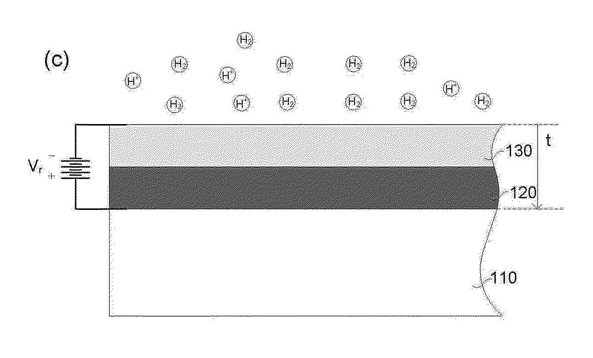
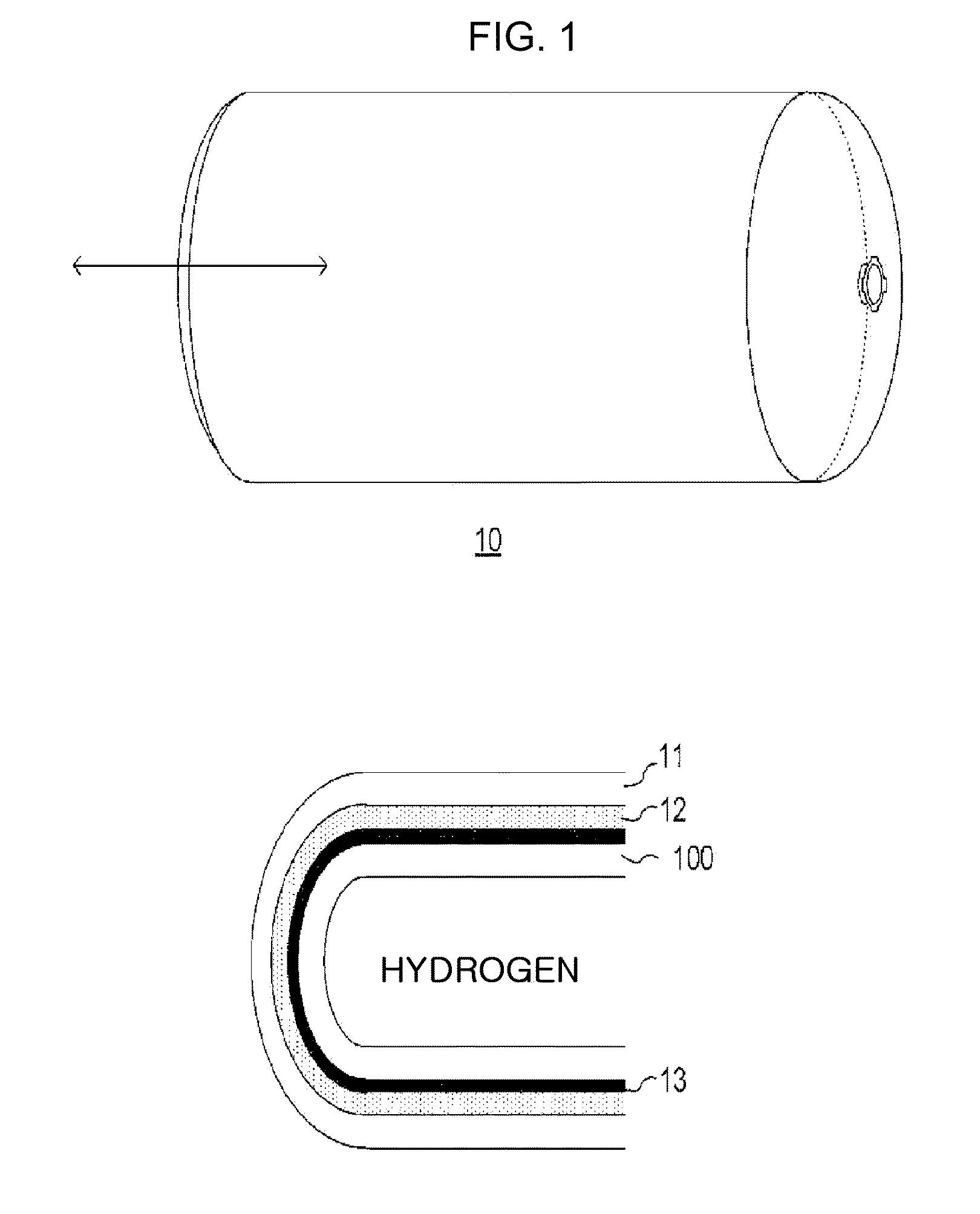
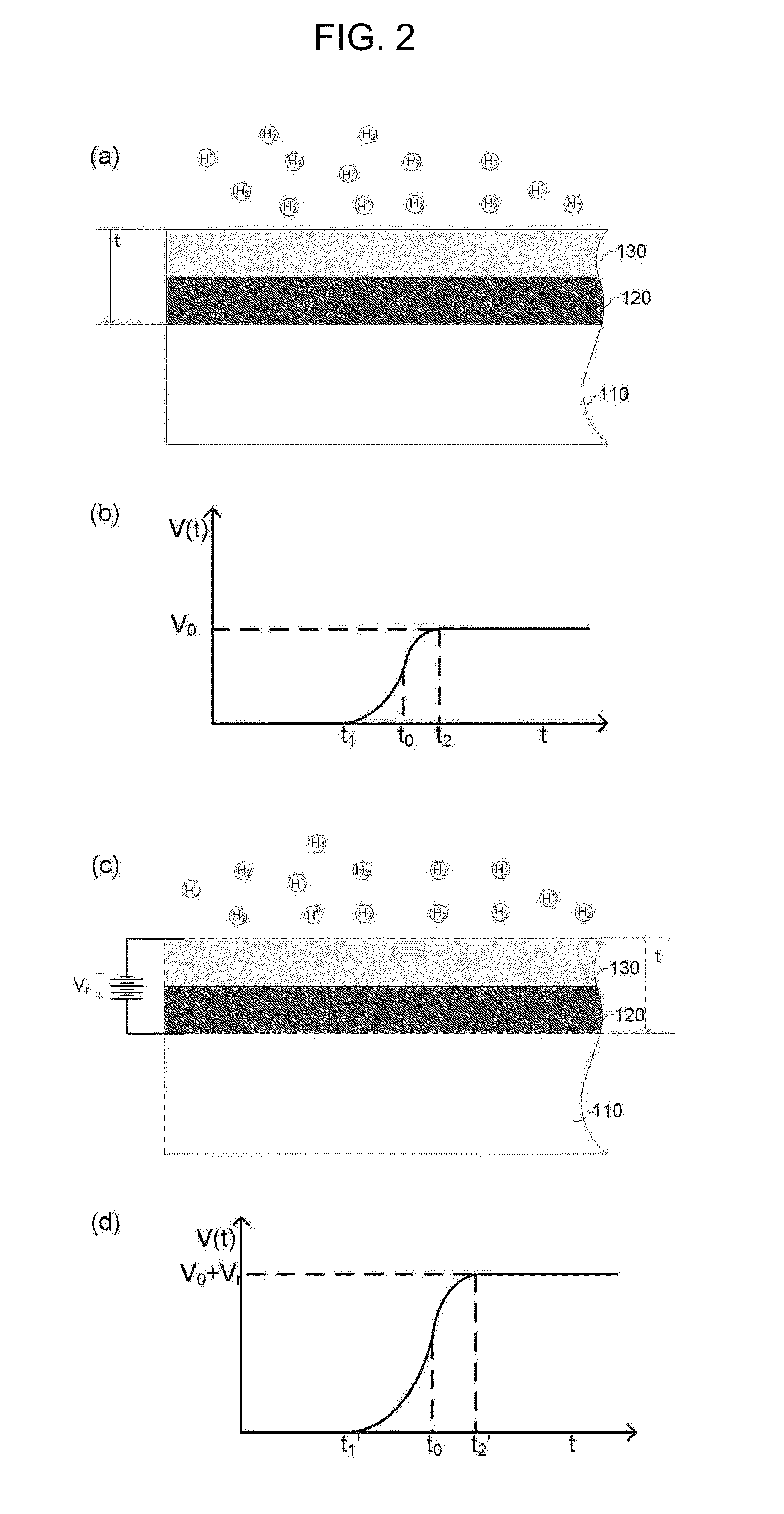
[0025]100: HYDROGEN PENETRATION BARRIER[0026]110: SUPPORT LAYER[0027]120: N-TYPE SEMICONDUCTOR LAYER[0028]130: P-TYPE SEMICONDUCTOR LAYER[0029]140: HYDROGEN ABSORPTION LAYER[0030]150: ELECTRODE[0031]141: CATALYST METAL PARTICLE

BEST MODE

[0032]A hydrogen penetration barrier according to an exemplary embodiment of the present invention will be described in more detail with reference to the accompanying drawings. The following introduced drawings are provided as an example in order to sufficiently transfer the idea of the present invention to those skilled in the art. The exemplary embodiment of the present invention is not limited to the following drawings and may be implemented as other types. In addition, like components are denoted by like reference numerals throughout the specification.

[0033]Unless explicitly described to the contrary, technical terms and scientific terms used herein have meanings so that they can be generally understood by those skilled in the art to which the pre...


PUM

PropertyMeasurementUnit
pressureaaaaaaaaaa
voltageaaaaaaaaaa
reverse biased voltageaaaaaaaaaa

Abstract

Provided is a hydrogen penetration barrier for preventing hydrogen from being diffused and discharged through a barrier and preventing hydrogen embrittlement of a material due to diffusion of hydrogen ions into a material. In detail, the hydrogen penetration barrier prevents penetration of hydrogen ions by using a built-in potential of a semiconductor layer doped with a p-type impurity and a semiconductor layer doped with an n-type impurity and a potential applied by a reverse biased voltage and includes an absorption layer absorbing the hydrogen molecules to primarily prevent the penetration of the hydrogen molecules and uses the absorption layer made of the conductive material as an application electrode of the reverse biased voltage and ionizes the hydrogen absorbed to the absorption layer to secondarily prevent the penetration of the hydrogen molecules and prevent the hydrogen embrittlement.

Description

TECHNICAL FIELD[0001]The present invention relates to a hydrogen penetration barrier for preventing hydrogen from being diffused and discharged through a barrier and preventing hydrogen embrittlement of a material due to diffusion of hydrogen ions into a material, and more particularly, to a penetration barrier for electrochemically preventing penetration of hydrogen by using a potential of a p-n junction to which a reverse biased voltage is applied.BACKGROUND ART[0002]In order to regulate carbon dioxide emissions, which is the main culprit of global warming, the Kyoto Protocol took effect in December, 1997. Thereafter, in order to control huge carbon dioxide emissions, research into a renewable and clean alternative energy source that is renewable and clean such as solar energy, wind power, water power, hydrogen energy, etc., has been actively conducted.[0003]Hydrogen has been spotlighted as clean alternative energy, which has been mainly used as an energy source of a fuel cell. Th...

Claims


Application Information

Patent Timeline
Patent Type & Authority Applications(United States)
IPC IPC(8): H01L51/30H01L29/16
CPCC01B3/503C21D3/00C01B3/508B01D63/00
Inventor KIM, YONG ILKIM, IN JUNGLEE, YUN-HEELEE, KYOUNG SEOKNAHM, SEUNG HOON
Owner KOREA RES INST OF STANDARDS & SCI
Why Eureka
Try Eureka