Magnetic assembly and method for defining a magnetic field for an imaging volume

a magnetic field and imaging volume technology, applied in the field of magnetic fields, can solve the problems of limited effectiveness, especially detrimental distortion, and geometric distortion in the resulting image, and achieve the effects of reducing the perturbation of patient dosimetry, reducing the size, and reducing the inhomogeneity of axisymmetric and/or non-axisymmetric field

Inactive Publication Date: 2011-07-21
ALBERTA HEALTH SERVICES
View PDF40 Cites 25 Cited by
  • Summary
  • Abstract
  • Description
  • Claims
  • Application Information

AI Technical Summary

Benefits of technology

[0012]The variety of magnetic fields across the inward-facing surfaces of the magnets enables production of a substantially homogenous magnetic field that is acceptable for imaging in an imaging volume, and that is of a sufficient size without necessarily resorting to use of very large magnets. As such, the production of a variety of magnetic fields across the inward-facing surfaces of the magnets provide a configuration that enables a more compact magnet assembly for a given imaging volume.
[0039]The method described herein can be applied to the computer-based design of magnetic assemblies for use in medical applications, particularly those involving Magnetic Resonance Imaging (MRI) where a bi-planar magnet configuration (eg. Helmholtz type) is to be employed. Such bi-planar magnet assemblies include those with spaced-apart first and second pole pieces with generally opposing first and second pole faces, such as, but not limited to, C-shaped magnets, two column magnets, or four column magnets. In such applications, the method can be utilized to produce magnet assemblies which produce a substantially uniform magnetic field in a particular imaging volume by way of reduction of axisymmetric and / or non-axisymmetric field inhomogeneities. More generally, the method described herein may be employed to produce a magnetic field with specially desired characteristics in a particular region within or proximate the magnetic assembly where additional objects or devices may be located whose operation may be affected by the presence and / or characteristics of the magnetic field. Such objects or devices may be x-ray tubes, medical linear accelerator waveguides (linac), flat-panel imagers, nuclear medicine or ultrasound imagers, or other devices. Such devices may be placed at the ends of the open space between the two poles. The method described herein is also applicable to the definition of a magnetic field in an imaging volume for magnet assemblies that include an opening in one or both of the magnet poles either in the centre or at any location, for positioning of any device at that location. Such placement may be provided for design or operational advantage, such as reduction in size and / or reducing perturbations in patient dosimetry in a treatment system that is integrated with imaging system and / or producing a particular magnetic field. For example, one particular configuration would be the positioning of a linear accelerator (linac) at a location within the magnet structure where the direction of electrons in the waveguide or photons produced by them is parallel to the magnetic field produced by the magnet thus decreasing the subsequent perturbations in patient radiation dosimetry.

Problems solved by technology

However, inhomogeneities in the static magnetic field within the imaging volume are inseparable from the magnetic field gradients during image acquisition and directly lead to geometric distortions in the resulting images.
These distortions are especially detrimental when the MRI system is to be used in conjunction with another procedure that relies on the geometric accuracy of the acquired images, such as, but not limited to, radiation therapy.
While shimming has in some applications been effective in limiting inhomogeneity in the imaging volume, its effectiveness is limited by the extent to which the initial field inhomogeneities are present after manufacturing.
As such, significant constraints are placed on the design of magnet assemblies, and by the requirement of maintaining a suitably large and accessible space within the magnet assembly for the object being examined.
Both such designs are limited in that points on the surface regions of the pole pieces located an identical radial distance from the axis are also located a common axial distance along the axis, and thus only axisymmetric magnetic field inhomogeneities can be reduced prior to shimming.
Furthermore, these systems are massive and immobile as the pole piece sizes are necessarily very large, and therefore are not suitable for movement relative to the subject being examined.
Unfortunately, current state of the art magnet assembly design does not address the effects of including objects or additional therapeutic or diagnostic devices within or proximate to the magnet assemblies, while providing acceptably homogeneous imaging volumes and / or other volumes with specific magnetic field properties, and ensuring that the size of the magnet assembly is manageable.
The operation of such additional devices may be affected by the presence and / or characteristics of the magnetic field at their location and may themselves alter the characteristics of the magnetic field in the imaging volume.

Method used


Image

  • Magnetic assembly and method for defining a magnetic field for an imaging volume
  • Magnetic assembly and method for defining a magnetic field for an imaging volume
  • Magnetic assembly and method for defining a magnetic field for an imaging volume

Examples


Embodiment Construction

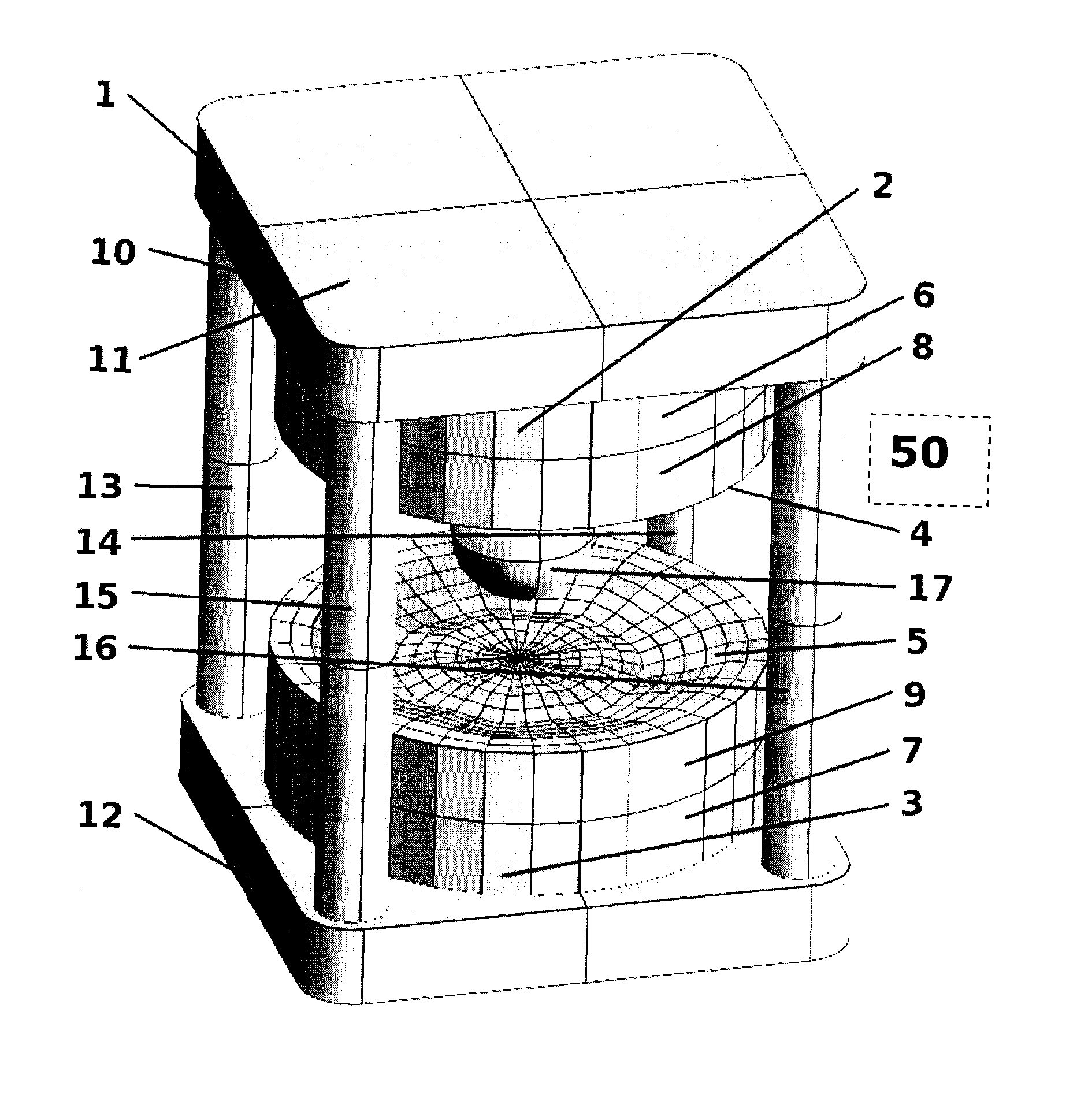
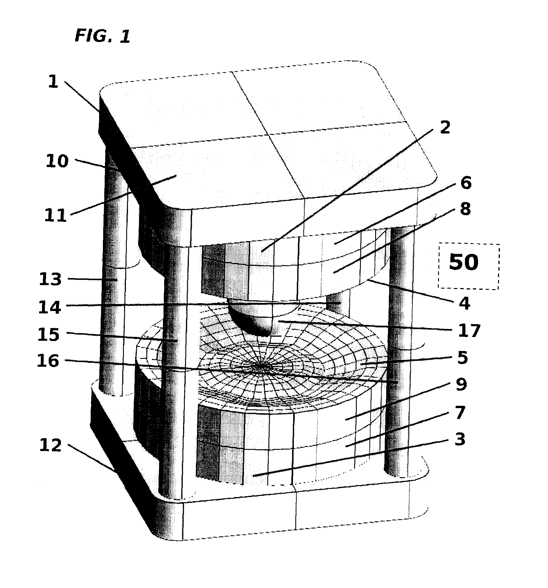
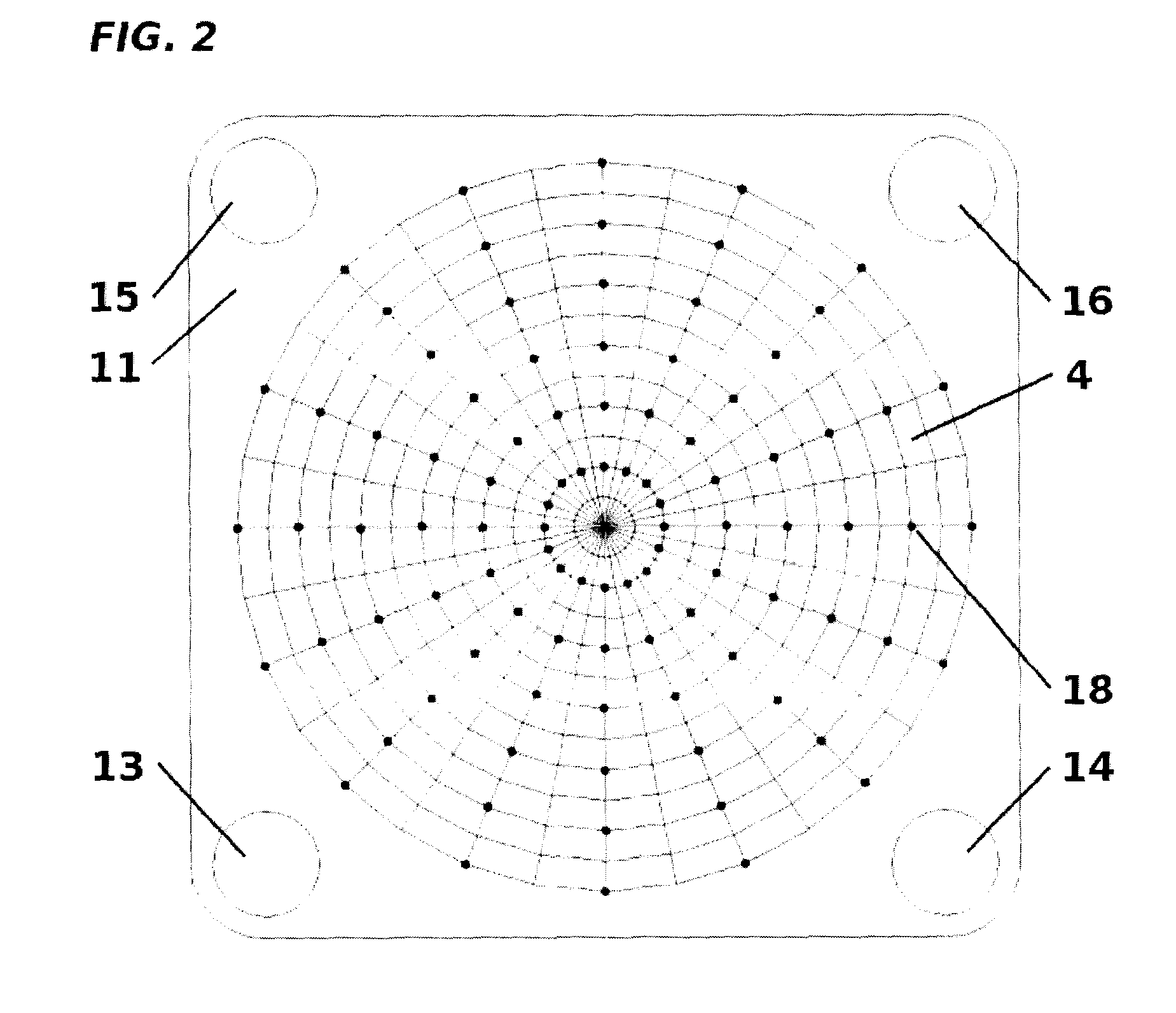
[0053]Referring now to the drawings wherein like numerals indicate like elements throughout, FIGS. 1-4 show a magnet assembly 1 according to an embodiment. In this embodiment, magnet assembly 1 includes a first ferromagnetic pole assembly 2 and a second ferromagnetic pole assembly 3. The first and second ferromagnetic pole assemblies 2, 3 are arranged in a fixed, spaced relationship with one another as “biplanar” magnets thereby to define a space therebetween that encompasses an imaging volume 17 and is large enough to receive an object (not shown) to be imaged at the imaging volume 17. The magnet assembly 1 is “open” as the object to be imaged can be moved between the pole assemblies 2, 3 to be positioned at the imaging volume 17.

[0054]In this embodiment, each of the first and second pole assemblies 2, 3 comprises both a cylindrical permanent magnet piece 6 (7) and a substantially cylindrical ferromagnetic piece 8 (9). The permanent magnet piece 6 (7) and substantially cylindrical ...


PUM

PropertyMeasurementUnit
static magnetic fieldaaaaaaaaaa
magnetic field strengthsaaaaaaaaaa
magnetic fieldaaaaaaaaaa

Abstract

Disclosed herein is a magnet assembly that includes at least two magnets arranged in a fixed spaced relationship with one another thereby to define a space between the magnets that encompasses an imaging volume. Each of the magnets produces a variety of magnetic field strengths across inward-facing surfaces thereof that, in combination, produce an acceptably homogeneous magnetic field in the imaging volume. Also disclosed is a method of defining a magnetic field for an imaging volume. The method comprises generating an initial model of a magnet assembly; estimating a magnetic field for the imaging volume based on the model; calculating deviation between the estimated magnetic field and a target magnetic field for the imaging volume; and updating the model to reduce the deviation by modifying the magnet assembly to produce a variety of magnetic field strengths that, in combination, produce substantially the target magnetic field in the imaging volume.

Description

CROSS-REFERENCE TO RELATED APPLICATION[0001]This application claims priority under 35 U.S.C. 119(e) from U.S. Provisional Patent Application Ser. No. 61 / 129,412 filed Jun. 24, 2008, the contents of which are entirely incorporated herein by reference.FIELD OF THE INVENTION[0002]The present invention relates generally to magnetic fields with predetermined specially desired characteristics, and more particularly to magnetic assembly and method for defining a magnetic field for an imaging volume.BACKGROUND OF THE INVENTION[0003]Magnetic Resonance Imaging, or MRI, is a well-known imaging technique during which an object, such as a human patient, is placed into an MRI machine and subjected to a uniform magnetic field produced by a polarizing magnet housed within the MRI machine. Radio frequency (RF) pulses, generated by an RF coil housed within the MRI machine, are used to scan target tissue of the patient. MRI signals are radiated by excited nuclei in the target tissue in the intervals b...

Claims


Application Information

Patent Timeline
Patent Type & Authority Applications(United States)
IPC IPC(8): H01F7/02G06G7/62
CPCA61N5/1043A61N2005/1087A61N2005/1089G01R33/3806G06F17/50G21K1/093H01F7/0278A61B5/055G01R33/543G01R33/383G06F30/00
Inventor FALLONE, B. GINOTADIC, TONYMURRAY, BRAD
Owner ALBERTA HEALTH SERVICES
Why Eureka
Try Eureka