

Microscale heat or heat and mass transfer system
- Summary
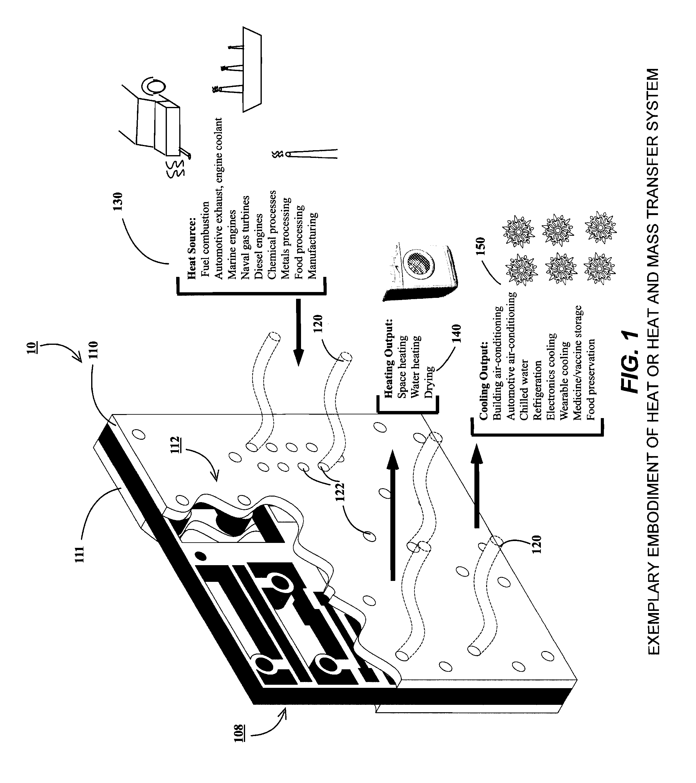
- Abstract
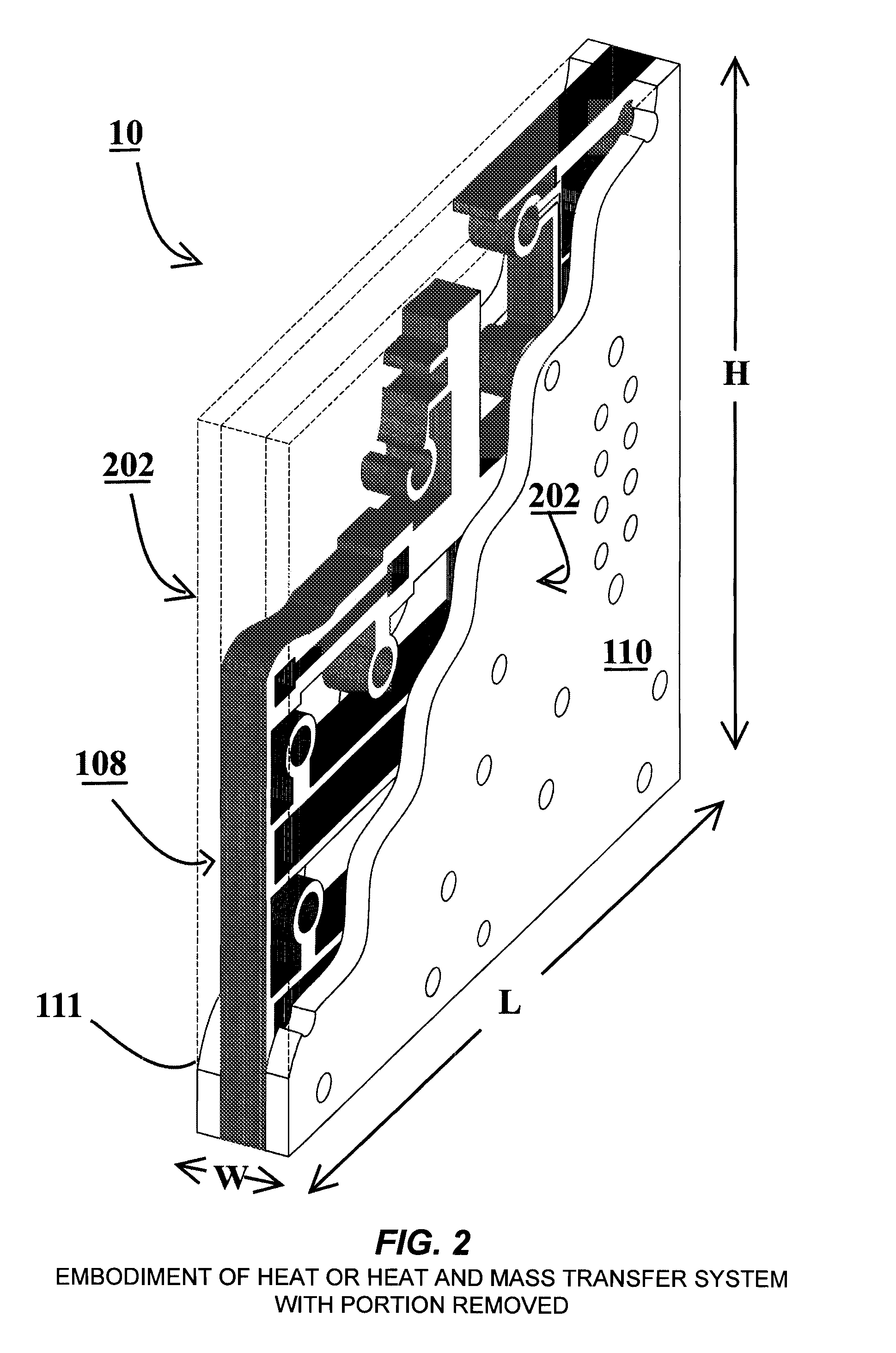
- Description
- Claims
- Application Information
AI Technical Summary
Benefits of technology
Problems solved by technology
Method used
Image


Examples
Embodiment Construction
[0042]Prior to a detailed description of the disclosure, the following definitions are provided as an aid to understanding the subject matter and terminology of aspects of the present systems and methods, are exemplary, and not necessarily limiting of the aspects of the systems and methods, which are expressed in the claims. Whether or not a term is capitalized is not considered definitive or limiting of the meaning of a term. As used in this document, a capitalized term shall have the same meaning as an uncapitalized term, unless the context of the usage specifically indicates that a more restrictive meaning for the capitalized term is intended. However, the capitalization or lack thereof within the remainder of this document is not intended to be necessarily limiting unless the context clearly indicates that such limitation is intended.
Definitions / Glossary
[0043]Absorbent: material or fluid that, either by itself or in multi-component form combined with ammonia or another refrigera...
PUM
 Abstract
Description
Claims
Application Information