

Hydrogen generator system for a catalytic hydrogen burner
a hydrogen generator and catalytic technology, applied in the direction of fuel cell, fuel energy technology, electrical-based machining apparatus, etc., can solve the problems of lowering the performance of the system, high cost, and more limited duration, and achieve the effect of improving performance and sufficient purity
- Summary
- Abstract
- Description
- Claims
- Application Information
AI Technical Summary
Benefits of technology
Problems solved by technology
Method used
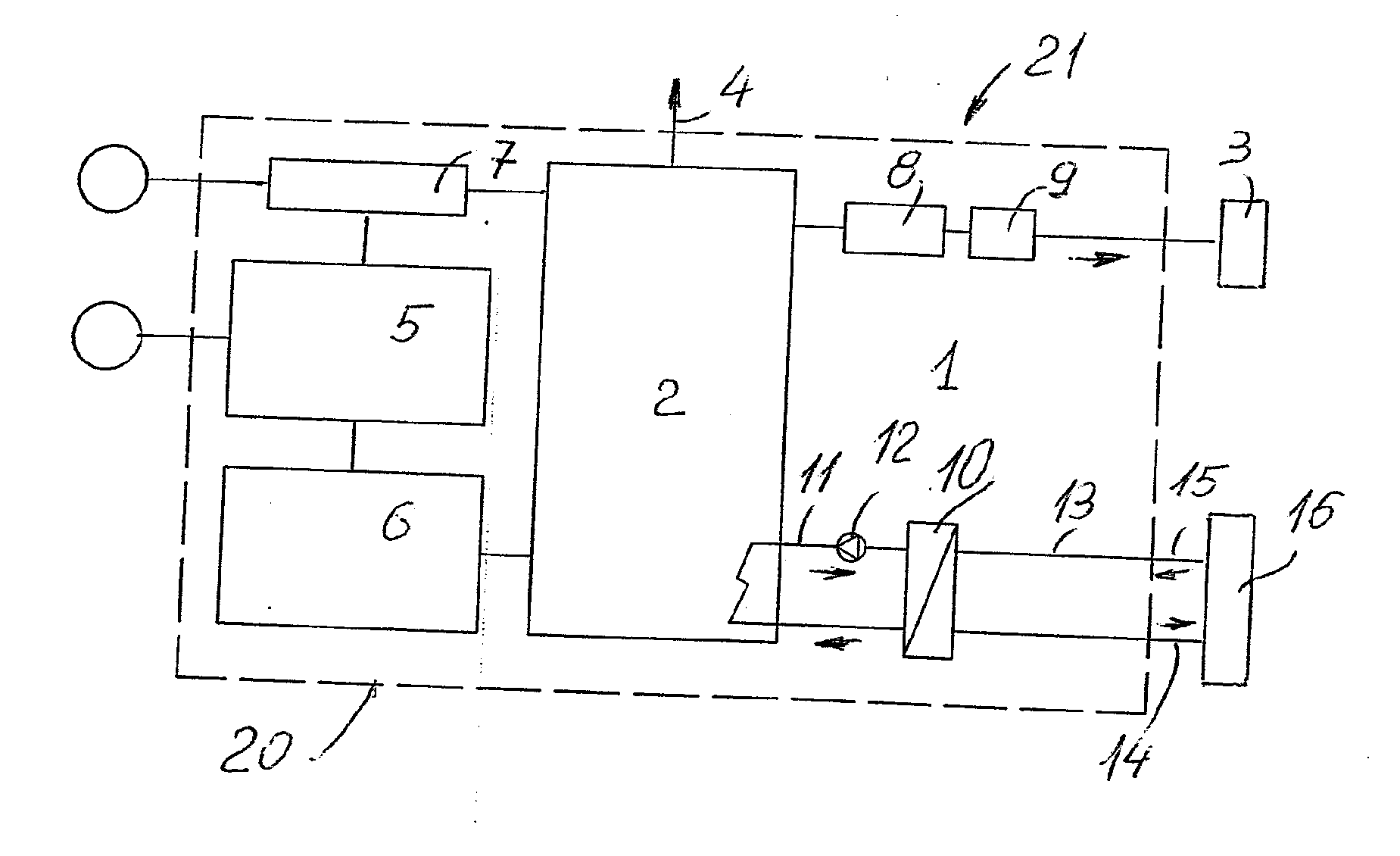
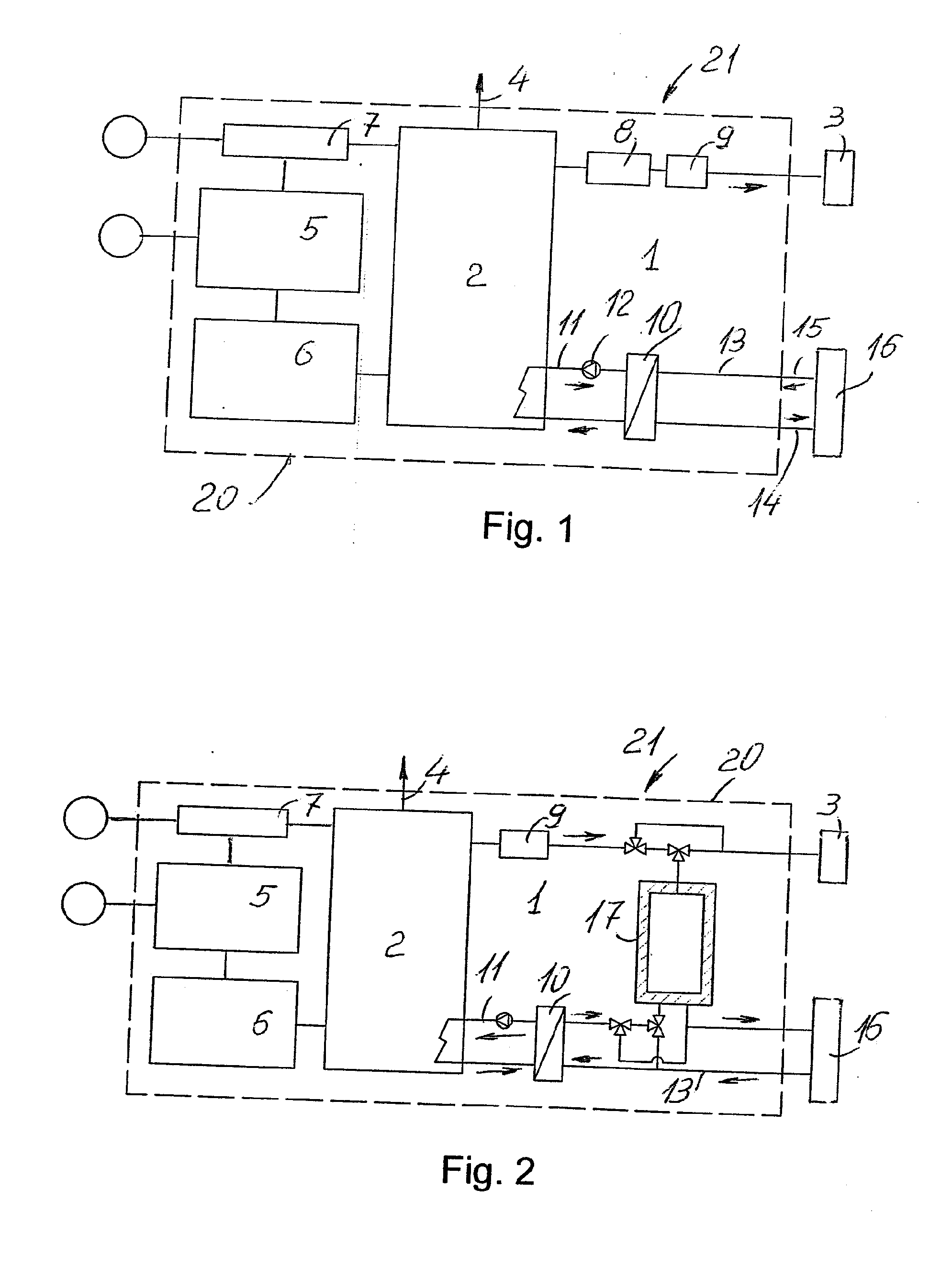
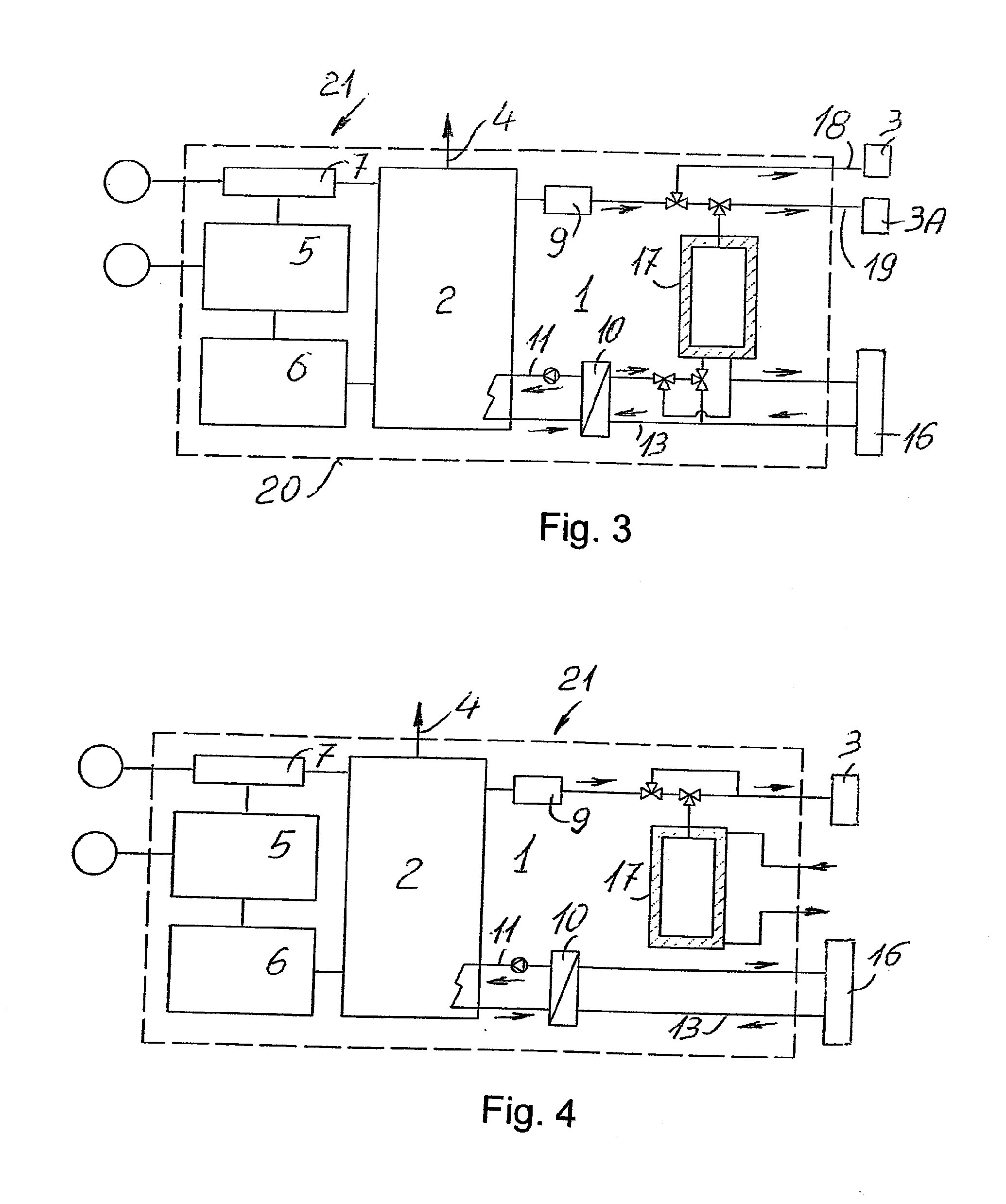
Image

Examples
example 1
[0053]Project Data:
[0054]User: 5.8 kW catalytic burner, 1.67 Nm3 / h hydrogen consumption
[0055]Storage duration: 12 hours
[0056]Duration of recharge cycle: 12 hours
[0057]Hypothesis for drawing solely from the storage and not directly from the producer.
[0058]Dimensioning:
Minimumdimensionofthestoragemeans=1.67m3h·12h=20m3=20000lMinimumelectrolyserflowrate=2m3h
[0059]Where the required flow rate was rounded off to the higher number for a safety factor and to near the flow rates available in the market.
[0060]Amount of distilled water required to fill the
storagemeans=20m3·0.87lm3=17.4l
[0061]Where 0.87 represents the standard consumption of the electrolyser. A 20 litre storage means is assumed for the sake of safety.
Minimumwatertreatmentflowrate=20l÷12h=1.67lh
[0062]N.B. In this calculation example, the m3 shall be considered under normal conditions.
[0063]Results:
[0064]Water treatment (minimum flow rate)=1.67 l / h
[0065]Demineralised water storage=20 litres
[0066]Electrolysis (rec...
example 2
Fuel Cell
[0068]Project Data:
[0069]User: 1 kW fuel cell, 14 litres / minute hydrogen consumption
[0070]Storage duration: 8 ore
[0071]Duration of recharge cycle: 12 ore
[0072]Hypothesis for drawing solely from the storage and not directly from the electrolyser.
[0073]Dimensioning:
User=14litresmin·601000=0.84m3h≃1m3h
[0074]In this dimensioning, the maximum consumption of hydrogen was rounded off to the higher value so as to have a safety margin.
Minimumdimensionofthestoragemeans=1m3h·8h=8m3=8000lMinimumflowrateoftheelectrolyser=8m3÷12h=0.67m3h
[0075]Amount of distilled water required to fill the
storagemeans=8m3·0.87lm3=6.96l
[0076]Where 0.87 is the standard consumption of an electrolyser. A 10 litre storage means is assumed for the sake of safety.
Minimumwatertreatmentflowrate=10l÷12h=0,83lh
[0077]In this calculation example, the m3 shall be considered under normal conditions.
Results:
[0078]Water treatment (minimum flow rate)=0.83 l / h
[0079]Demineralised water storage=10 litres
[0080]Electrolysis (mi...
PUM
| Property | Measurement | Unit |
|---|---|---|
| pressure | aaaaa | aaaaa |
| pressures | aaaaa | aaaaa |
| pressure | aaaaa | aaaaa |
Abstract
Description
Claims
Application Information