
Methods of obtaining panoramic images using rotationally symmetric wide-angle lenses and devices thereof

a technology of rotational symmetry and wide-angle lens, which is applied in the field of mathematically precise image processing methods of extracting panoramic images, can solve the problems of less than 50% of pixel utilization, inefficient use of pixels, and large number of unused pixels in the image sensor, so as to achieve accurate image processing the effect of images

Inactive Publication Date: 2011-07-28
NANOPHOTONICS CO LTD
View PDF11 Cites 45 Cited by
  • Summary
  • Abstract
  • Description
  • Claims
  • Application Information

AI Technical Summary

Benefits of technology

"The present invention relates to methods for extracting panoramic images from images captured using a panoramic camera. The invention provides precise and accurate methods for extracting panoramic images that appear natural to the naked eye. The invention also includes devices that use these methods, such as panoramic imaging systems for capturing panoramic images of buildings, nature scenes, and tourist resorts. The invention is useful for security and surveillance applications, as well as for navigational aids for mobile robots and unmanned aerial vehicles. The invention is based on the use of a cylindrical object plane and a refractive lens to capture the image of an object on the object plane. The invention provides a more natural and seamless view of the world, allowing for improved visual experiences."

Problems solved by technology

One disadvantage of such a panoramic imaging system is that there are considerable numbers of unused pixels in the image sensor. FIG. 6 is a schematic diagram illustrating the degree of pixel utilization on the sensor plane(613) of an image sensor having the standard 4:3 aspect ratio.
Thus, the percentage of pixel utilization is less than 50%, and the panoramic imaging systems of prior arts have a disadvantage in that pixels are not efficiently used.
In such cases, it is inefficient if the horizontal field of view is significantly larger than 180°.
This is because a wall, which is not needed to be monitored, takes up a large space in the monitor screen, pixels are wasted, and screen appears dull.
Nevertheless, a fisheye lens with 180°FOV is not desirable for such application.
This is because the barrel distortion, which accompanies a fisheye lens, evokes psychological discomfort and abhorred by the consumer.
The shortcomings of a pan•tilt•zoom camera include high price, large size and heavy weight.
Optical zoom lens is large, heavy and expensive due to the difficulty in design and the complicated structure.
Also, a pan•tilt stage is an expensive device not cheaper than a camera.
Therefore, it cost a considerable sum of money to install a pan•tilt•zoom camera.
Furthermore, since a pan•tilt•zoom camera is large and heavy, this fact can become a serious impediment to certain applications.
Furthermore, pan•tilt•zoom operation takes a time because it is a mechanical operation.
Therefore, depending on the particular application at hand, such a mechanical response may not be fast enough.
However, the environment was not a real environment captured by an optical lens, but a computer-created imaginary environment captured with an imaginary distortion-free pinhole camera.
But, the real projection scheme of a fisheye lens generally shows a considerable deviation from an ideal equidistance projection scheme.
Nevertheless, the defect of not showing vertical lines as vertical lines in the monitor screen has not been resolved.
Distortion is unavoidable if we want to describe the scene of every 360° direction on a two-dimensional plane.
Similar difficulty exists in the cartography where geography on earth, which is a structure on the surface of a sphere, needs to be mapped on a planar two-dimensional atlas.
Among all the distortions, the distortion that appears most unnatural to the people is the distortion where vertical lines appear as curved lines.
Nevertheless, it is disadvantageous in that the size of a geographical area is greatly distorted.
However, the panoramic image appears unnatural when the latitudinal range is large, and thus it is not widely used in practice.
Thus, although the error may be less than that of FIG. 10, still the exemplary panoramic image in FIG. 11 does not satisfy the proportionality relation given by Eq.
This method requires a complex, time-consuming, and elaborate operation of precisely joining several pictures and correcting the lens distortion.
In other words, the techniques described in the documents make it possible to obtain an omnidirectional image from a real environment or from a cubic panorama, but the obtained omnidirectional image follows an equidistance projection scheme only and its usefulness is thus limited.
Nevertheless, the real projection scheme of the fisheye lens in the said reference is inconvenient to use because it has been modeled with the real image height on the film plane as the independent variable, and the zenith angle of the incident ray as the dependent variable.
Furthermore, unnecessarily, the real projection scheme of the fisheye lens has been modeled only with odd polynomials.

Method used


Image

  • Methods of obtaining panoramic images using rotationally symmetric wide-angle lenses and devices thereof
  • Methods of obtaining panoramic images using rotationally symmetric wide-angle lenses and devices thereof
  • Methods of obtaining panoramic images using rotationally symmetric wide-angle lenses and devices thereof

Examples


first embodiment

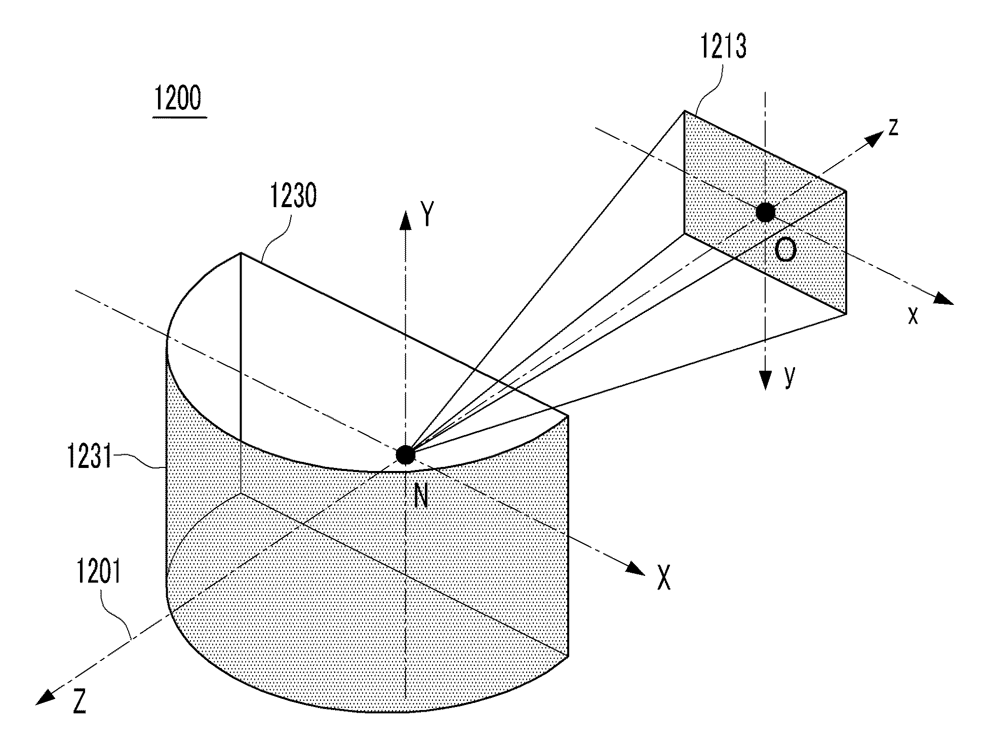
[0125]FIG. 12 is a schematic diagram for understanding the field of view and the projection scheme of a panoramic imaging system according to the first embodiment of the present invention. The panoramic imaging system of the current embodiment is assumed as attached on a vertical wall(1230), which is perpendicular to the ground plane. The wall coincides with the X-Y plane, and the Y-axis runs from the ground plane (i.e., X-Z plane) to the zenith. The origin of the coordinate is located at the nodal point N of the lens, and the optical axis(1201) of the lens coincides with the Z-axis (in other words, it is parallel to the ground plane). Hereinafter, this coordinate system is referred to as the world coordinate system. The world coordinate system is a coordinate system for describing the environment around the camera that is captured by the lens, and it is a right-handed coordinate system.

[0126]In a rigorous sense, the direction of the optical axis is the direction of the negative Z-a...

second embodiment

[0209]As has been stated previously, a cylindrical projection scheme in the strict sense of the words is not used widely. Although it provides a mathematically most precise panoramic image, the image does not appear natural to the naked eye when the vertical FOV (i.e., Δδ=δ2−δ1) is large.

[0210]The cylindrical projection scheme of the first embodiment can be generalized as follows. The lateral coordinate x″ on the processed image plane is proportional to the horizontal incidence angle. Therefore, as in the first embodiment, a relation given in Eq. 75 holds.

A=WΔψ=x″ψ[MathFigure75]

[0211]On the other hand, the longitudinal coordinate y″ on the processed image plane is proportional to a monotonic function of the vertical incidence angle as given in Eq. 76.

y″∝F(δ)  [Math Figure 76]

[0212]Here, F(δ) is a continuous and monotonic function of the vertical incidence angle δ. Therefore, a relation given by Eq. 77 corresponding to the Eq. 22 holds as follows.

A=HF(δ2)-F(δ1)=y″F(δ)[MathFigure77]

[0...

third embodiment

[0232]Field of view of typical wide-angle lenses used in security and surveillance area is 90° at the maximum, and a security lens having this amount of FOV generally exhibits a considerable degree of distortion. A lens having a FOV larger than this is not widely used because such a lens exhibits excessive distortion and causes psychological discomfort.

[0233]FIG. 34 is a conceptual drawing of an imaging system(3400) for monitoring the entire interior space using a typical wide-angle camera having a FOV near 90°. Usually, security cameras must be installed at a high place that is out of reach from the people. Therefore, in order to monitor the entire interior place while kept out of reach from the people, the camera(3410) is installed at a corner where the ceiling and two walls meet, and camera is facing down toward the interior. The optical axis(3401) of the camera is inclined both against a horizontal line and a vertical line, and the camera captures the objects(3467) at a slanted ...


PUM


Abstract

The present invention provides methods of obtaining panoramic images that appear most natural to the naked eye by executing a mathematically precise image processing operation on a wide-angle image acquired using a wide-angle lens that is rotationally symmetric about an optical axis, and devices using the methods. Imaging systems using this method can be used not only in security surveillance applications for indoor and outdoor environments, but also in diverse areas such as video phones for apartment entrance doors, rear view cameras for vehicles, visual sensors for unmanned aerial vehicles and robots, and broadcasting cameras. Also, it can be used to obtain panoramic photographs using digital cameras.

Description

TECHNICAL FIELD[0001]The present invention generally relates to mathematically precise image processing methods of extracting panoramic images, which appear most natural to the naked eye, from images acquired using a camera equipped with a wide-angle lens that is rotationally symmetric about an optical axis, as well as devices using the methods.BACKGROUND ART[0002]Panoramic camera, which captures the 360° view of scenic places such as tourist resorts, is an example of a panoramic imaging system. Panoramic imaging system is an imaging system that captures the views one could get by making one complete turn-around from a given spot. On the other hand, omnidirectional imaging system captures the view of every possible direction from a given spot. Omnidirectional imaging system provides a view that a person could observe from a given position by turning around as well as looking up and down. In a mathematical terminology, the solid angle of the region that can be captured by the imaging...

Claims


Application Information

Patent Timeline
Patent Type & Authority Applications(United States)
IPC IPC(8): H04N5/225H04N23/75
CPCG03B37/00H04N5/23238H04N5/232G06T1/00H04N23/698H04N23/63H04N23/695H04N23/00H04N23/75
Inventor KWEON, GYEONG-IL
Owner NANOPHOTONICS CO LTD
Learn More