Sequestration of a gas emitted by an industrial plant

a technology of industrial plants and gas sequestration, applied in the direction of separation processes, cell components, sulfur compounds, etc., can solve the problems of only effective mea methods, parasitic power losses, and capital intensive sequestration methods, and achieve the effect of reducing greenhouse and flue gas emissions

Inactive Publication Date: 2011-07-28
RUTGERS THE STATE UNIV
View PDF50 Cites 42 Cited by
  • Summary
  • Abstract
  • Description
  • Claims
  • Application Information

AI Technical Summary

Benefits of technology

[0011]The gas is thus separated from the gas absorber, which can be recycled for use in a subsequent gas absorption step or other process, thereby eliminating the need of a stripping tower in a power generating or other industrial plant.

Problems solved by technology

In addition, industrial processes, such as steel making, glass melting and ceramic manufacturing, are large contributors to carbon dioxide emissions (e.g., cement, 0.79 Mt / year / plant).
This method of forming an adduct, driving off carbon dioxide and subsequent underground storage of carbon dioxide, while qualifying as a method of sequestration, is capital intensive, expensive and hardly ideal, as discussed further below.
First, the MEA method is only effective when the temperature is sufficiently low to facilitate carbon dioxide adduct formation and avoid MEA decomposition.
Thus, there is an energy cost for cooling the solution resulting in parasitic power losses, which also generate CO2 by virtue of the additional power demands placed on the power grid.
Second, the stripping tower needed to separate carbon dioxide from MEA also has associated with it operational costs because of the significant amount of energy needed to heat the MEA-CO2 adduct solution to about 120° C. The large volume of solution, which needs to be heated, leads to a large energy input and additional parasitic power loss to the power grid.
Third, pressurization of the carbon dioxide step is also a high cost step with accompanying parasitic energy loss (by “parasitic” is meant that the energy produced by a power plant, which ideally would be transmitted via a gird to customers, is sapped by the energy needs of the conventional method being described), where compressors are needed to achieve supercritical pressures of about 14 MPa (2000 lb / in2) or more.
Although storage of the carbon dioxide by injection underground is possible for select locations around the world, the pipeline and maintenance costs further increase the capital investment and operational costs.
Overall, these cost issues can increase the cost of products (e.g., electricity) by tens of a percent, with a number as high as 81% being reported.
Nevertheless, a certain amount of energy consumption for the solvent regeneration is still unavoidable.
In addition, the capitalization of conventional CCS equipment is costly, and thus the increase in costs for power plant construction can rise by as much as 87%.
In addition to concerns related to cost, greenhouse gas emission, energy and electricity production rate, there are ecological concerns regarding the consequences of storing CO2 in geological formations and beneath the ocean.
Long-term storage of a gaseous substance is fraught with uncertainty and unknown hazards.

Method used


Image

  • Sequestration of a gas emitted by an industrial plant
  • Sequestration of a gas emitted by an industrial plant
  • Sequestration of a gas emitted by an industrial plant

Examples


working examples

NON-LIMITING WORKING EXAMPLES

Example A

CO2 Sequestration and MEA Regeneration from Mineral (Alumino)Silicates

example a1

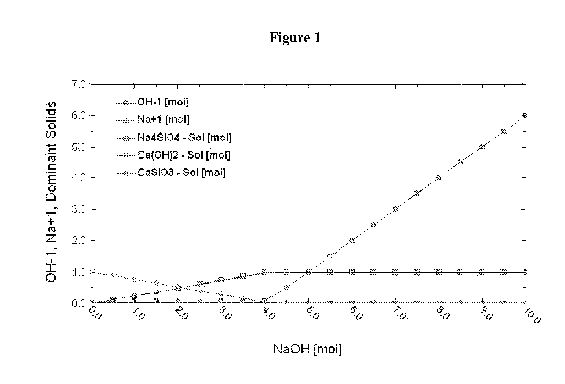
Wollastonite (CaSiO3)

[0098]

2CaSiO3+4NaOH→Na4SiO4(s)+2Ca(OH)2  Reaction 1

MEA(aqueous solution)+CO2→MEA-CO2(l)  Reaction 2

MEA-CO2(l)+Na4SiO4(s)+2Ca(OH)2→2CaCO3(s)+Na4SiO4(s)+MEA(l)  Reaction 3

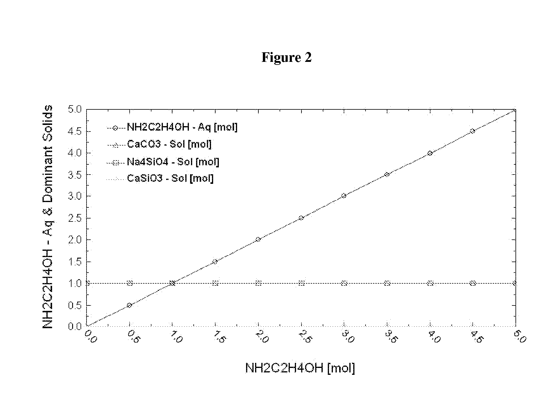
[0099]Thermodynamic simulation shows that when [NaOH] is about 4 M, 1 molal wollastonite is completely dissolved (as shown by x-intercept of the curve representing wollastonite in FIG. 1) to produce 1 mol Ca(OH)2 and 1 mol Na4SiO4 solid (see FIG. 1) and Na4SiO4 solid has no influence on the reaction of MEA-CO2 and Ca(OH)2 (see FIG. 2).

[0100]1) 2 g CaSiO3 was added into 100 ml 4M NaOH solution and heated for 6 hours under 500 rpm agitation at 90° C. 7 g Ca(OH)2 and 9 g Na4SiO4 were formed. CO2 saturated 30 wt % MEA solution was added into the solid formed as described above and the solution was stirred at 500 rpm for 10 minutes. XRD analysis of the final product suggests the presence of CaCO3.

example a2

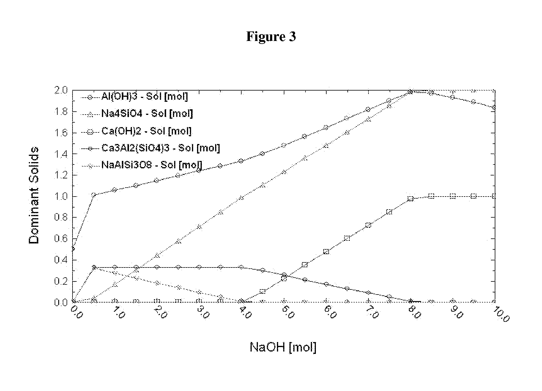
Anorthite (CaAl2Si2O8)

[0101]

CaAl2Si2O8+8NaOH→2Na4SiO4(s)+Ca(OH)2+2Al(OH)3  Reaction 1

MEA(aqueous solution)+CO2→MEA-CO2(l)  Reaction 2

MEA-CO2(l)+2Na4SiO4(s)+Ca(OH)2+2Al(OH)3→MEA(l)+CaCO3(s)+2Al(OH)3(s)+2Na4SiO4(s)  Reaction 3

[0102]Thermodynamic simulation shows that when [NaOH] is about 8 M, 1 molal anorthite can be completely dissolved to produce 1 mol Ca(OH)2 and 2 mol Na4SiO4 solid and 2 mol Al(OH)3 (see FIG. 3). Al(OH)3 and Na4SiO4 solids have no influence on the reaction of MEA-CO2 and Ca(OH)2 (see FIG. 4).

[0103]28 g CaAl2Si2O8 was added into 100 ml 8 M NaOH solution. The solution was heated at 90° C. for 1 day under 500 rpm agitation. 7 g Ca(OH)2, 36 g Na4SiO4 and 15 g Al(OH)3 were produced. CO2-saturated 30 wt % MEA solution was added into the solid formed as described above and the solution was stirred at 500 rpm for 10 minutes. XRD analysis of the final product suggested the presence of CaCO3.


PUM

PropertyMeasurementUnit
porosityaaaaaaaaaa
porosityaaaaaaaaaa
temperatureaaaaaaaaaa

Abstract

A method of sequestering a multi-element gas emitted by an industrial plant is described herein, the method comprising: contacting a solution, including a first reactant comprising a multi-element gas emitted by an industrial plant and at least one gas absorber comprising nitrogen, for example ammonia or an amine, with a solid, including a second reactant, under conditions that promote a reaction between the first reactant and the second reactant to provide a first product, which incorporates one or more elements of the multi-element gas, thereby sequestering the multi-element gas.

Description

[0001]This application claims priority to U.S. Provisional Application No. 61 / 297,646, filed on Jan. 22, 2010, which is incorporated herein by reference.[0002]All references cited herein are incorporated by reference in their entirety. Cross-reference is made to U.S. application Ser. No. ______ (attorney docket number 32867.004.01) filed concurrently with this application.BACKGROUND[0003]Gas emissions from industrial plants, like electrical power plants, such as coal-fired systems, are a major concern due to their immense volume—at tens of giga-ton (Gt) masses of carbon dioxide (CO2) emission, which are emitted, on average, about 4 mega-tons (Mt) / year / plant (IPCC report, ISBN 92-9169-119-4). Currently, over 2100 coal-fired power plants (not to mention countless other industrial plants, including manufacturing plants, assembly plants and the like, which emit one or more gases) account for about 33% of all U.S. CO2 emissions, corresponding to about 2 Gt / year (Science, vol. 317, 184 (2...

Claims


Application Information

Patent Timeline
Patent Type & Authority Applications(United States)
IPC IPC(8): C01C1/18C01F11/18C01F5/42C01G49/12C01B31/20C07D295/027C07C213/08C07C215/40C01B32/50
CPCB01D53/1425B01D2258/0283B01D53/50B01D53/52B01D53/62B01D53/68B01D2252/102B01D2252/2041B01D2252/20415B01D2252/20442B01D2252/20447B01D2252/20484B01D2252/20489B01D2252/20494B01D2257/2027B01D2257/2047B01D2257/302B01D2257/304B01D2257/504B01D53/1456
Inventor RIMAN, RICHARD E.LI, QINGHUA
Owner RUTGERS THE STATE UNIV
Why Eureka
Try Eureka