Bones which have been fractured, either by accident or severed by surgical procedure, must be kept together, for lengthy periods of, time in order to permit the recalcification and bonding of the severed parts. Accordingly, adjoining parts of a severed or
fractured bone are typically clamped together or attached to one another by means of plates, pins or screws driven through the rejoined parts. Movement of the pertinent part of the body may then be kept at a minimum, such as by application of a cast, brace, splint, or other
conventional technique, in order to promote healing and avoid mechanical stresses that may cause the bone parts to separate during bodily activity. The surgical procedure of attaching two or more parts of a bone with a pin-like device normally requires an incision into the tissue surrounding the bone and the drilling of a hole through the bone parts to be joined. Due to the significant variation in bone size, configuration, and load requirements, a wide variety of
bone fixation devices have been developed in the prior art. In general, the current methods rely upon a variety of
metal wires, screws, plates and clamps to stabilize the bone fragments during the healing process. Following a sufficient
bone healing period of time, the site may require re-opening to permit removal of the
bone fixation device.
The ankle joint is a comparatively small joint relative to the
weight bearing and torque it must withstand. Total ankle replacement systems attempting to address
pain control and improved function have in the past experienced significant failure rates due to the technical difficulty of simulating ankle geometry and loadings. The main alternative to total ankle replacement is arthrodesis. Both procedures are intended to reduce pain but the total ankle replacement is additionally intended to improve function. If an arthrodesis or ankle replacement is not properly aligned, significant
gait abnormalities may result. The principal limitations of past total ankle replacement have been loosening of the
prosthesis, requiring revision. If the
prosthesis requires removal, a subsequent arthrodesis can be considered. Different prostheses require different amounts of removal of bone, potentially compromising the success of a subsequent arthrodesis. Some ankles with
implant components often require revision or arthrodesis.
Ankle arthrodesis is currently a widely accepted surgical procedure but good, uniform results are not always achievable. Patients treated by compression ankle arthrodesis do not always have an effective
fusion rate. The commonly used
external fixation devices afford stability in only one plane and do not give rigid immobilization. A device known as a Triangular
Compression Device has been used successfully. A successful Arthrodesis of the ankle can result in a painless, normal
walking gait. However, complications in ankle arthrodesis can be major, and can occur when
anatomy,
deformity, or bony deficiency is not properly addressed. Arthrodesis is usually considered after
conservative treatment (such as
arthroscopy) fails. Infections,
deformity, sensory deficiencies, and bony defects are complications which require special consideration. External compression enhances the likelihood of a successful arthrodesis.
Since the ankle is the only joint which to date does not have a specific plate for arthrodesis, there is a long felt want in the field to provide a fusion plate that is effective and useful in primary ankle fusion and which will reduce or eliminate fusion failure rates and which provides appropriate geometry to facilitate integrity of the screw bone interface, screw
insertion angle, screw tightness and effective
co operation between
screw head and the screw
insertion hole.
The present invention seeks to ameliorate or eliminate the aforesaid problems inherent in the prior art devices and apparatuses and particularly those used in ankle arthrodesis.
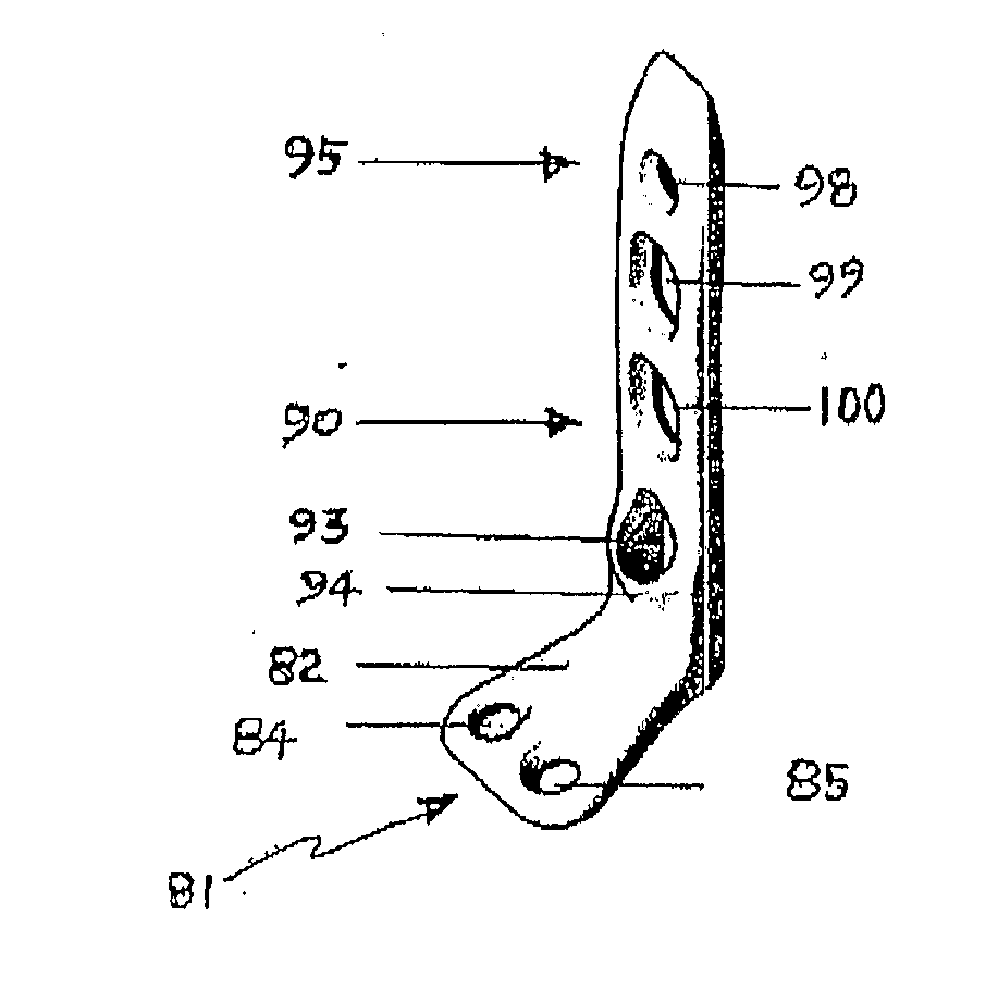
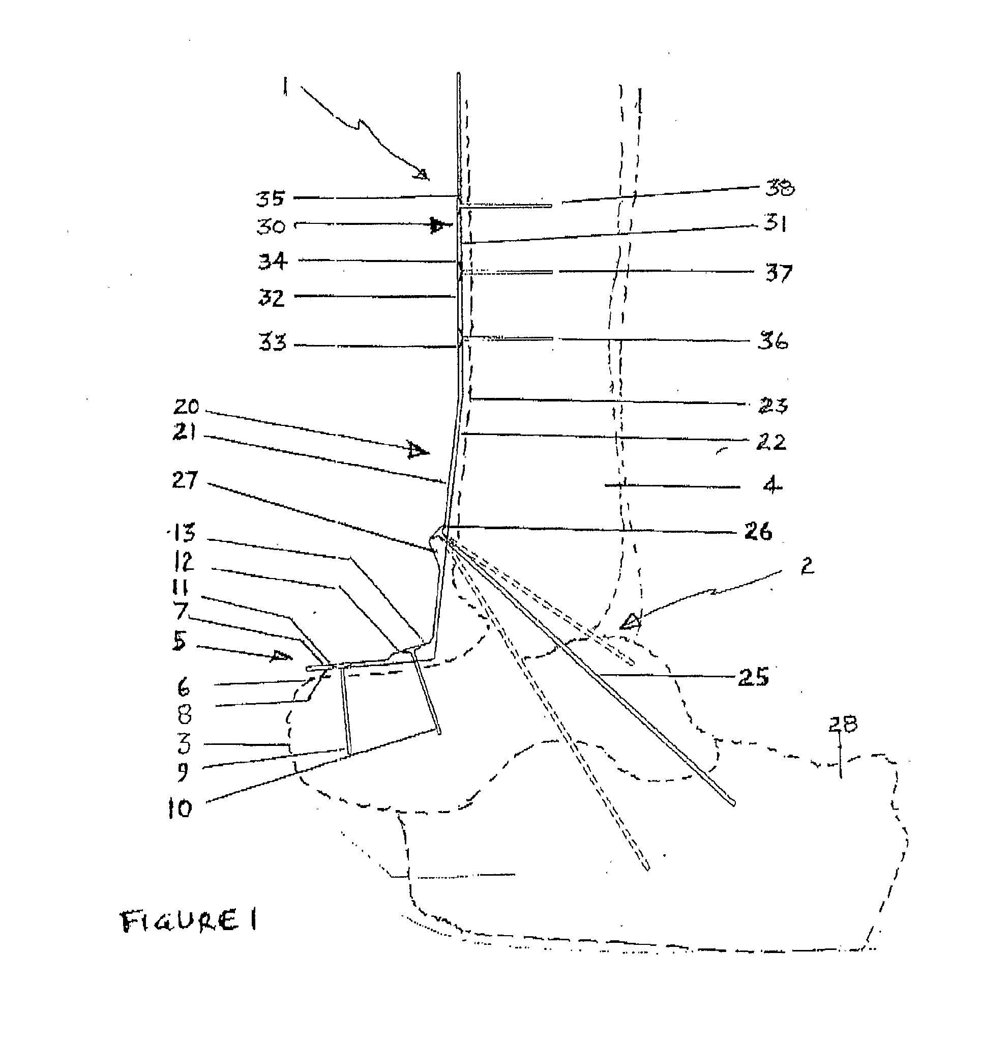
The present invention provides an improved arthrodesis fusion plate for fusion of the anterior ankle. More particularly the invention provides an ankle plate in which openings in the plate receive fixation screws allowing compression of bones being fused and orientation of the fixation screws to optimise
accommodation of bone loading for efficient and effective fusion. The invention further provides a method of insertion of an anterior ankle plate so that optimal compression is achieved and fixation screws are inserted at appropriate angles in anterior ankle
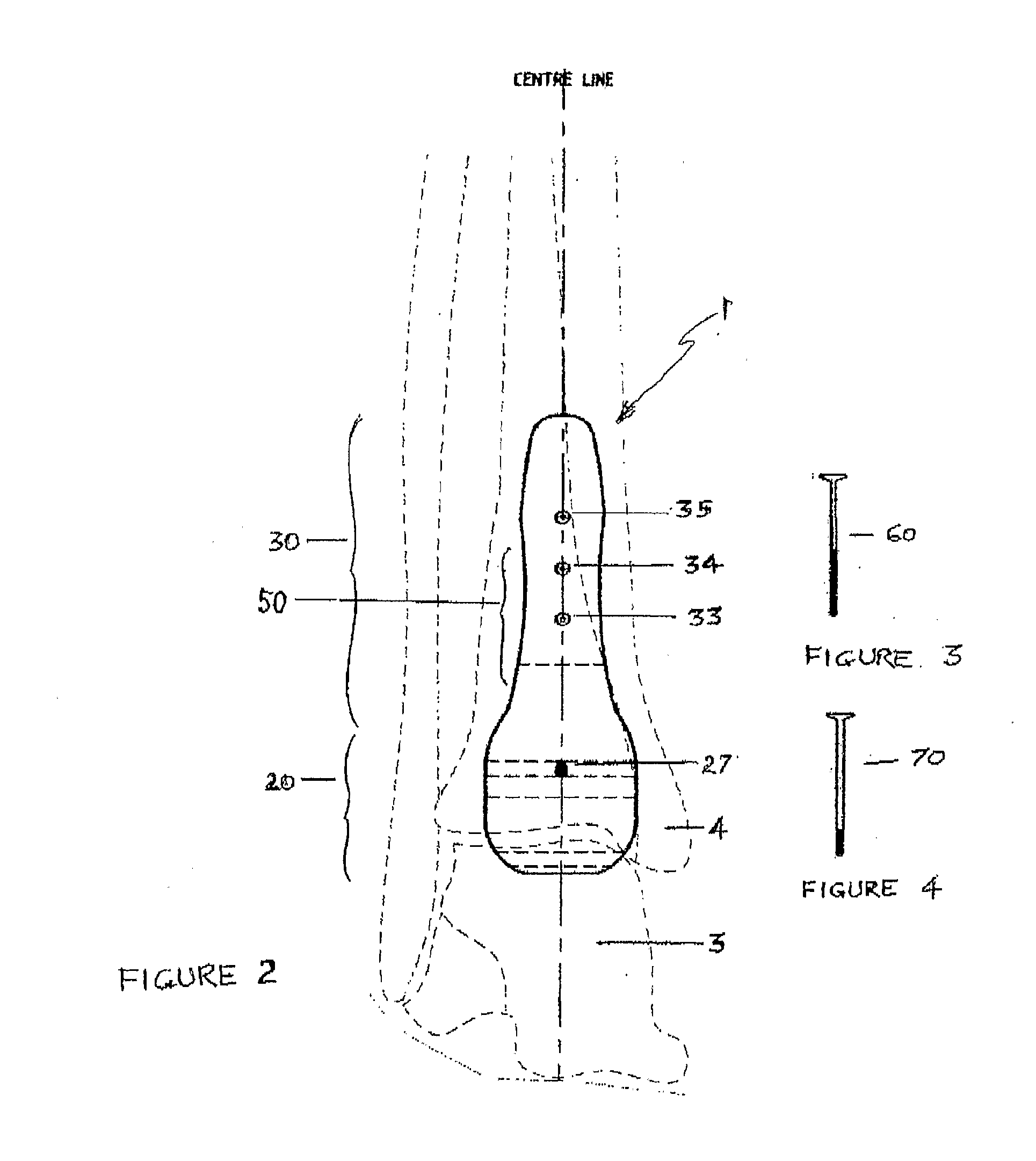
joint fusion. This invention further relates to a kit including an anterior ankle fusion plate and which includes a selection of fasteners for fixation of the ankle plate in a prescribed manner so that the orientation of the screws provide optimal, compression and
bone fusion.

