Grid and method of manufacturing a grid for selective transmission of electromagnetic radiation, particularly x-ray radiation for mammography applications

a technology of electromagnetic radiation and grid, which is applied in the direction of solid-state diffusion coating, nuclear engineering, discharge tube/lamp details, etc., can solve the problems of material loss, time-consuming and costly to manufacture such grid, and may be a highly complex three-dimensional structure that is not easily achievable, so as to reduce or simplify the handling of such grid, the effect of large area

Active Publication Date: 2011-08-11
KONINKLIJKE PHILIPS ELECTRONICS NV
View PDF7 Cites 9 Cited by
  • Summary
  • Abstract
  • Description
  • Claims
  • Application Information

AI Technical Summary

Benefits of technology

[0011]Accordingly, there may be a need for an improved method of manufacturing a grid for selective transmission of electromagnetic radiation which method may reduce or prevent the problems in connection with separating the grid from an underlying carrier substrate and/or which may simplify the handling of such grid during the ma

Problems solved by technology

As such two-dimensional anti-scatter-grids may need to have transmission channels that are focused to a focal spot of the radiation source that emits the primary radiation which shall be allowed to be transmitted through the grids, the grid may have to exhibit a sophisticated geometrical structure and it may be complicated, time-consuming and costly to manufacture such grid.
Having a structural element that is built by selective laser sintering, the grid may be a highly complex three-dimensional structure that is not easily achievable by conventional moulding or milling techniques.
A problem for the production of such large footprint grids may be the separation of the grid from a metal carrier that is normally

Method used


Image

  • Grid and method of manufacturing a grid for selective transmission of electromagnetic radiation, particularly x-ray radiation for mammography applications
  • Grid and method of manufacturing a grid for selective transmission of electromagnetic radiation, particularly x-ray radiation for mammography applications
  • Grid and method of manufacturing a grid for selective transmission of electromagnetic radiation, particularly x-ray radiation for mammography applications

Examples


Embodiment Construction

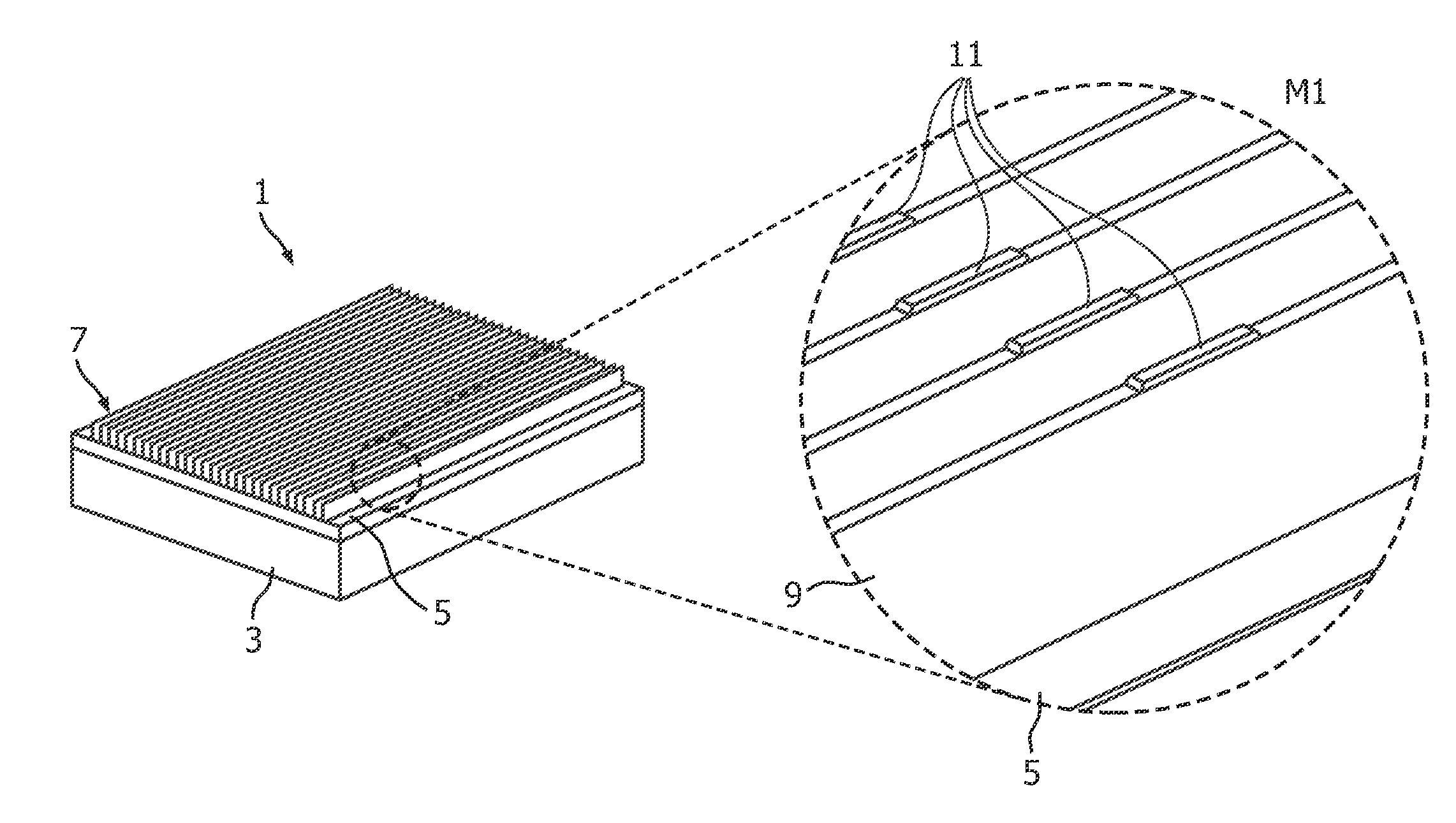
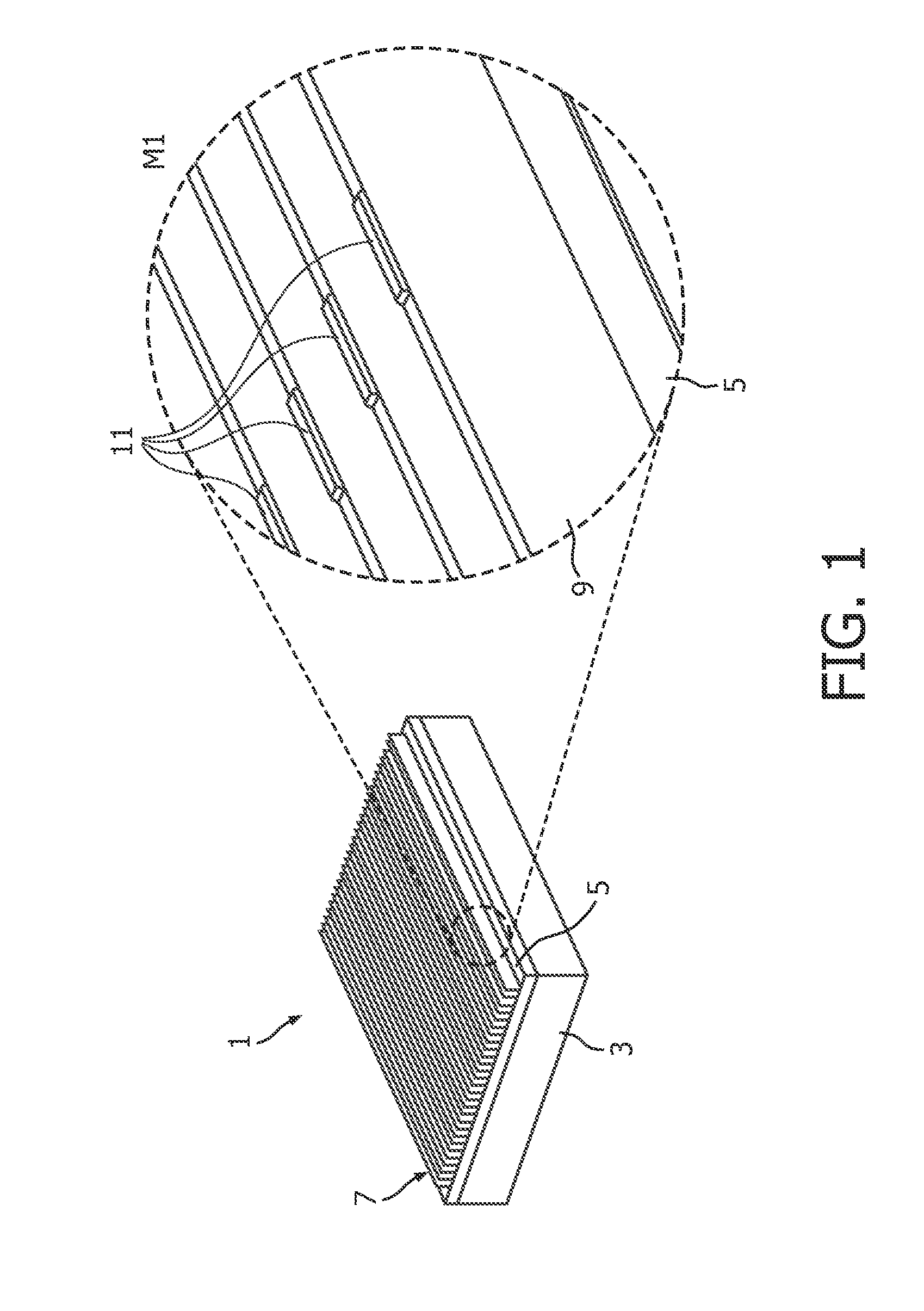
[0046]An exemplary embodiment of a method of manufacturing a grid 1 for selective transmission of electromagnetic radiation according to the invention will be described with reference to FIGS. 1, 2 and 3.

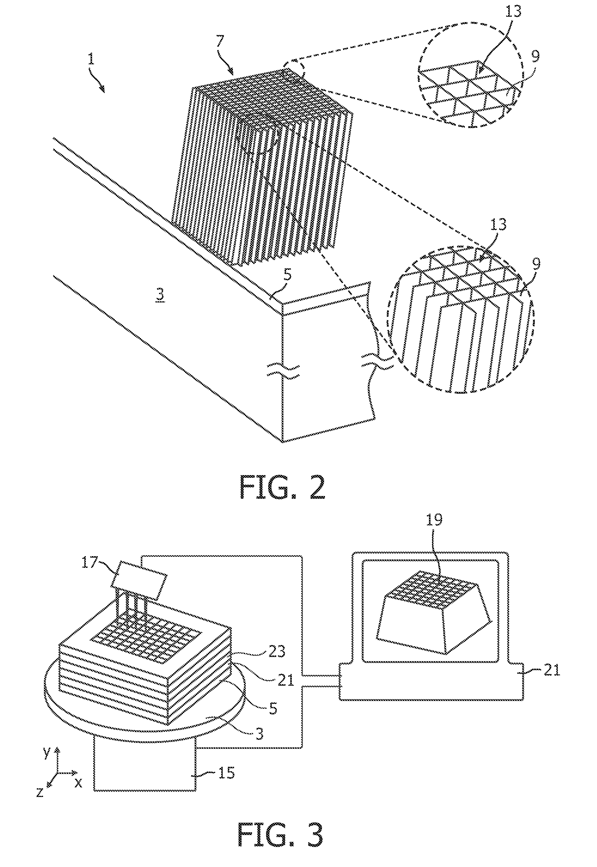
[0047]In a first step, a support element 3 having self-supporting stability and being made for example with carbon fibres is coated with a thin layer 5 of metal such as molybdenum or tungsten. The thus coated support element is then positioned in a working chamber of a selective laser sintering device. The precise positioning with respect to the position of the laser beam of the SLS device may be achieved by a previous system calibration. The metal layer 5 may serve as a base layer or seeding layer for the subsequent laser sintering process. After a layer of metal powder is arranged on the metal sheet, selective laser sintering is used to sinter a first layer of a sintered selective transmission structure 7 to be manufactured. After the first layer is completed, a next layer of meta...


PUM

PropertyMeasurementUnit
Thicknessaaaaaaaaaa
Adhesion strengthaaaaaaaaaa
Mechanical stabilityaaaaaaaaaa

Abstract

A method of manufacturing a grid (1) for selective transmission of electromagnetic radiation, particularly X-ray radiation, is proposed. The method comprises: providing a support element (3) having self-supporting stability, wherein the support element (3) is made with a material which essentially absorbs no electromagnetic radiation to be selectively transmitted through the grid; applying a metal layer (5) at a surface of the support element (3); and building a selective transmission structure (7) at a surface of the metal layer (5) with a material which absorbs electromagnetic radiation to be selectively transmitted through the grid, wherein the transmission structure is build using selective laser sintering. As the support element (3) provides sufficient mechanical stability but does not absorb the respective radiation, the selective transmission structure (7) build thereon using selective sintering might not have to be subsequently separated from a manufacturing substrate thereby preventing separation/dicing losses and, furthermore, might be structurally held and protected against damage during handling of the grid.

Description

FIELD OF THE INVENTION[0001]The present invention relates to a method of manufacturing a grid for selective transmission of electromagnetic radiation, particularly X-ray radiation for mammography applications. Furthermore, the present invention relates to a corresponding grid and to a medical imaging device comprising such grid.BACKGROUND OF THE INVENTION[0002]Grids for selective transmission of electromagnetic radiation may be used for example in medical imaging devices such as Computed Tomography scanners (CT), standard X-ray scanners like C-arm devices or mammography devices, Single Photon Emission Computed Tomography devices (SPECT) or Positron Emission Tomography scanners (PET). Other devices such as non-destructive X-ray testing devices may also use such grids. The grid may be positioned between a source of electromagnetic radiation such as an X-ray radiation source and a radiation-sensitive detection device. For example, in a CT scanner, the source of electromagnetic radiatio...

Claims


Application Information

Patent Timeline
IPC IPC(8): G21K1/00B05D3/06B32B37/06B32B38/00B44C1/22C23C14/34
CPCG21K1/025B22F3/1055B33Y10/00B33Y80/00Y02P10/25B22F10/28B22F12/30
Inventor VOGTMEIER, GEROEN
Owner KONINKLIJKE PHILIPS ELECTRONICS NV
Why Eureka
Try Eureka