Cast Metal Parts With Cosmetic Surfaces And Methods Of Making Same

a technology of cast metal parts and cosmetic surfaces, which is applied in the field of casting metal parts, can solve the problems of high porosity of die cast metals and cast metals made by other casting operations, affecting the appearance of the finished product, and the surface of cast metals undesirable for cosmetic anodization surface treatment, etc., to achieve the effect of improving or achieving the desired functional properties, increasing corrosion resistance and wear resistan

Inactive Publication Date: 2011-08-11
APPLE INC
View PDF23 Cites 22 Cited by
  • Summary
  • Abstract
  • Description
  • Claims
  • Application Information

AI Technical Summary

Benefits of technology

[0008]A cast metal part or article can have another metal applied the surface of the cast metal. The metal applied to the surface of the cast metal can be a cosmetic metal veneer with different properties from the cast metal whereby the cast metal part is imparted with the properties of the cosmetic metal. Surface treatments such as anodization can be successfully applied to the metal veneer to achieve a desired aesthetic appearance that may not be obtained if the same surface treatment were applied to a cast metal surface. The metal veneer can also provide the cast metal part with a surface that can have improved or desired functional properties that may be lacking in the underlying cast metal. For example, anodized metal surfaces can provide increased corrosion resistance and wear resistance, and can also provide a porous substrate conducive to absorbing dyes to impart a color to the anodized metal surface.

Problems solved by technology

However, die cast metals, and cast metals made by other casting operations, can have a high porosity due to air entrapment and shrinkage during the casting process.
The porosity and high content of silicone in cast metals, especially die cast metals, make the surface of cast metals undesirable for cosmetic anodization surface treatments.
This is because the porous surface of the cast metal tends to streak due to silicone leaching from the alloy metal.

Method used


Image

  • Cast Metal Parts With Cosmetic Surfaces And Methods Of Making Same
  • Cast Metal Parts With Cosmetic Surfaces And Methods Of Making Same
  • Cast Metal Parts With Cosmetic Surfaces And Methods Of Making Same

Examples


Embodiment Construction

[0023]The present application will be described with reference to the accompanying drawings, in which like reference numerals refer to similar elements. While specific configurations and arrangements are discussed, it should be understood that this is done for illustrative purposes only. A person skilled in the pertinent art will recognize that other configurations and arrangements can be used without departing from the spirit and scope of the present invention. It will be apparent to a person skilled in the pertinent art that this invention can also be employed in a variety of other applications. Moreover, for brevity, “metal part” is used throughout the present application interchangeably with “metal article”, and as used herein “metal part” should be considered synonymous with “metal article”, and can refer to stand alone articles and / or metal parts thereof.

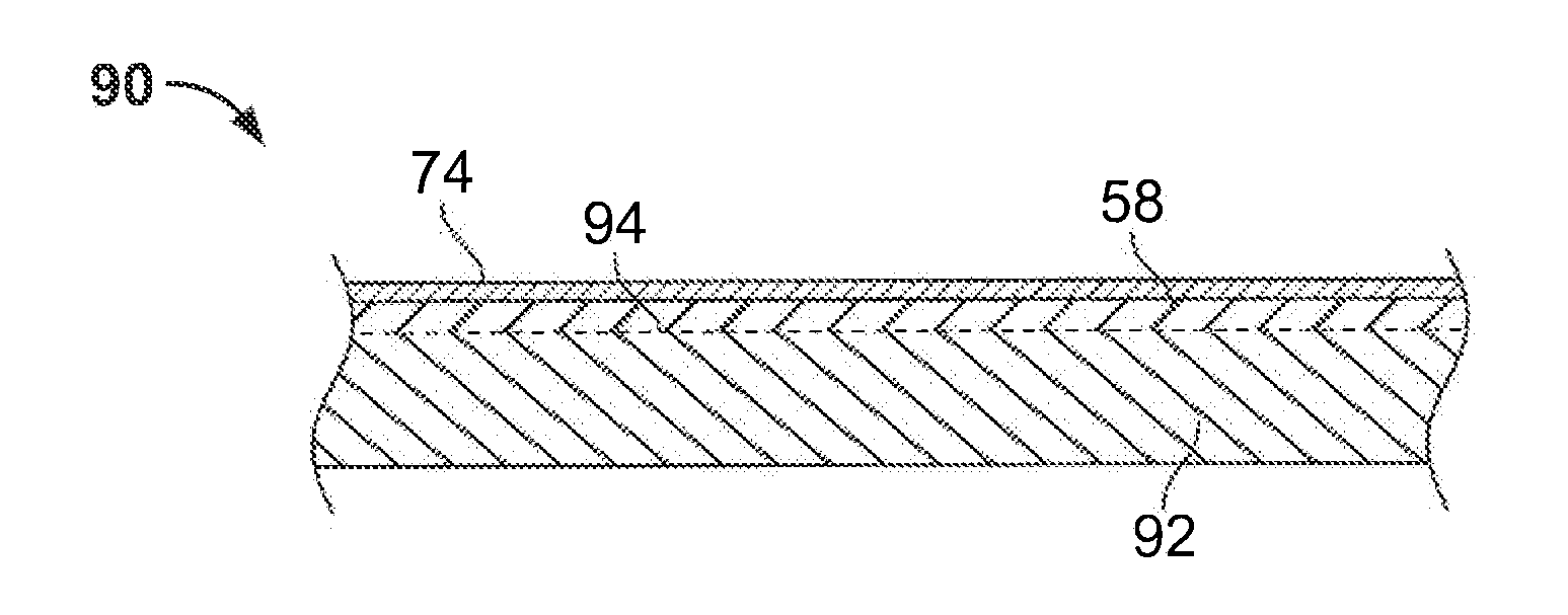
[0024]A cast metal part can have another metal applied the surface of the cast metal. The metal applied to the surface of th...


PUM

PropertyMeasurementUnit
thicknessaaaaaaaaaa
thicknessaaaaaaaaaa
thicknessaaaaaaaaaa

Abstract

A cast metal part has a veneer made of cosmetic metal applied thereto so that the cast metal part has a cosmetic surface. A method for producing a cast metal part with a cosmetic surface comprises applying a veneer of cosmetic metal to a surface of the cast metal part. The cast metal part can be a die cast part, such as die cast aluminum or zinc. The veneer can be thin gauge highly cosmetic aluminum. The veneer of cosmetic metal can be applied to the surface of the cast metal part by placing the veneer into a casting mold used for forming the cast metal part, and casting molten metal onto the veneer in the casting mold. The veneer of cosmetic metal can also be applied to the surface of the cast metal part by solid-state welding, e.g., diffusion bonding, the veneer and the cast metal part together.

Description

CROSS-REFERENCE TO RELATED APPLICATION[0001]This application claims the benefit of U.S. Provisional Application No. 61 / 302,842, filed Feb. 9, 2010, the entire disclosure of which is incorporated in its entirety herein by reference thereto.BACKGROUND OF THE INVENTION[0002]1. Field of the Invention[0003]The present invention relates to cast metal parts, and more particularly, the present invention relates to applying a cosmetic metal to a cast metal part so that the resulting cast metal part is a monolithic structure having a surface formed of the cosmetic metal.[0004]2. Background Art[0005]Many products in the commercial and consumer industries are metal articles, or contain metal parts. The metal surfaces of these products may be treated by any number of processes to alter the surface to create a desired effect, either functional, cosmetic, or both. One example of such a surface treatment is anodization. Anodizing a metal surface converts a portion of the metal surface into a metal ...

Claims


Application Information

Patent Timeline
Patent Type & Authority Applications(United States)
IPC IPC(8): B32B15/01B22D25/00B22D19/00
CPCB23K20/021B23K20/2336B23K2203/10B32B15/016Y10T428/12493C22F1/05C23C6/00C23C26/00C23C28/00C22C21/02B23K2103/10
Inventor ZADESKY, STEPHENPASMOOIJ, DUCO
Owner APPLE INC
Why Eureka
Try Eureka