Focused ion beam apparatus

a technology of focusing ion beams and focusing beams, applied in the direction of beam deviation/focusing by electric/magnetic means, instruments, mass spectrometers, etc., can solve the problems of complex structure, unstable ion beam irradiation, and apparatus having adjustment mechanisms suffer from costliness, so as to achieve the effect of alleviating the variation of ion beam curren

Active Publication Date: 2011-08-25
HITACHI HIGH TECH SCI CORP
View PDF5 Cites 6 Cited by
  • Summary
  • Abstract
  • Description
  • Claims
  • Application Information

AI Technical Summary

Benefits of technology

[0013]Accordingly, only the ion beam near the center of an optical axis of the ion beam ejected from the gas field ion gun unit is allowed to pass through the opening. Therefore, since only the ion beam near the center of the optical axis of the ion beam is allowed to enter the focusing lens, the peripheral component of the ion beam is prevented from being mixed with the central component. Therefore, the sample can be irradiated with a favorable beam having a preferable beam profile with a regular shape.
[0014]In the focused ion beam apparatus according to the invention, the lens system is arranged on the side of the sample with respect to the aperture. Accordingly, incoming of unnecessary components of the ion beam into the lens system can be alleviated. If impurity gas ionized without reaching the tip exists in the ion generating chamber, the ionized impurity gas is contained in the ion beam and varies the current amount as unnecessary component of the ion beam. Therefore, the ion beam may become unstable. By restricting the ion beam entering the lens system with the aperture, variation of the ion beam current can be alleviated.

Problems solved by technology

However, the adjusting mechanism as described above has a complex structure, and hence the apparatus having the adjustment mechanism suffers from its costliness.
It is often difficult with this mechanism to irradiate the ion beam stably, because the tip is subjected to vibrations.

Method used


Image

  • Focused ion beam apparatus
  • Focused ion beam apparatus
  • Focused ion beam apparatus

Examples


example 1

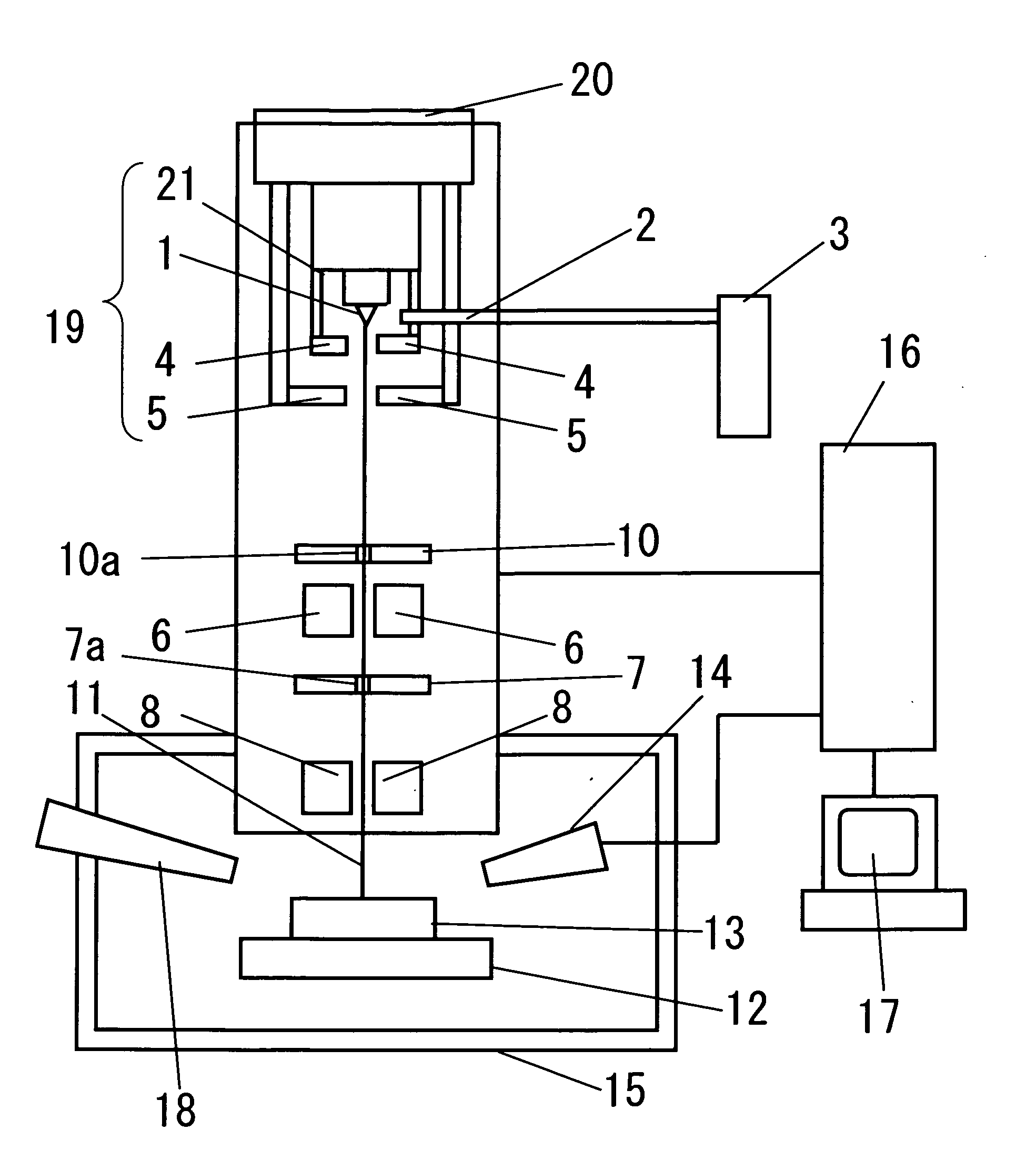
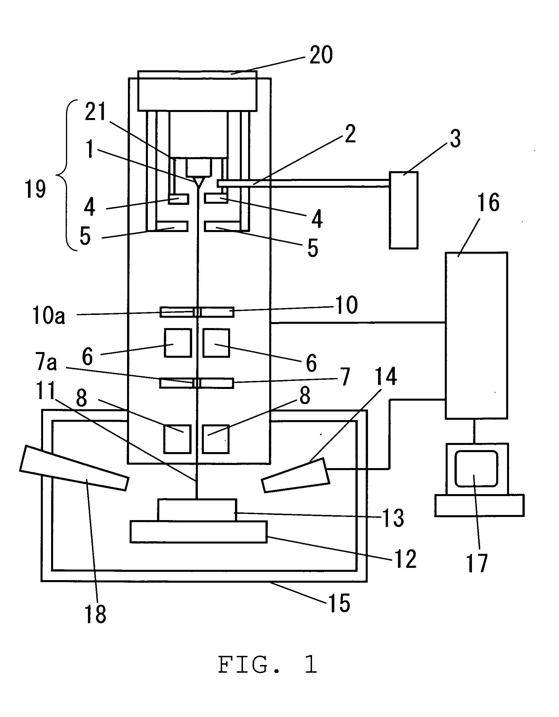
[0072]A method of beam adjustment according to the embodiment will be described. The opening 10a having the largest diameter on the second aperture 10 is arranged on the axis of irradiation of the ion beam 11. The adjustment mechanism 20 is operated while observing a secondary electron image in a state in which the ion beam is irradiated from the tip 1 of the ion gun unit 19, and the position of the ion gun unit 19 with respect to the lens system where a large amount of the ion beam reaches the sample 13 is searched.

[0073]The voltage applied to the objective lens electrode 8 is varied at the position of the ion gun unit 19 where the large amount of ion beam reaches the sample 13, and the voltage applied to the gun alignment electrode 9 is adjusted so that the secondary electron image does not move even when the voltage is varied.

[0074]Subsequently, the voltage applied to the focusing lens electrode 6 is varied, and the adjusting mechanism 20 is operated to adjust the position of the...

example 2

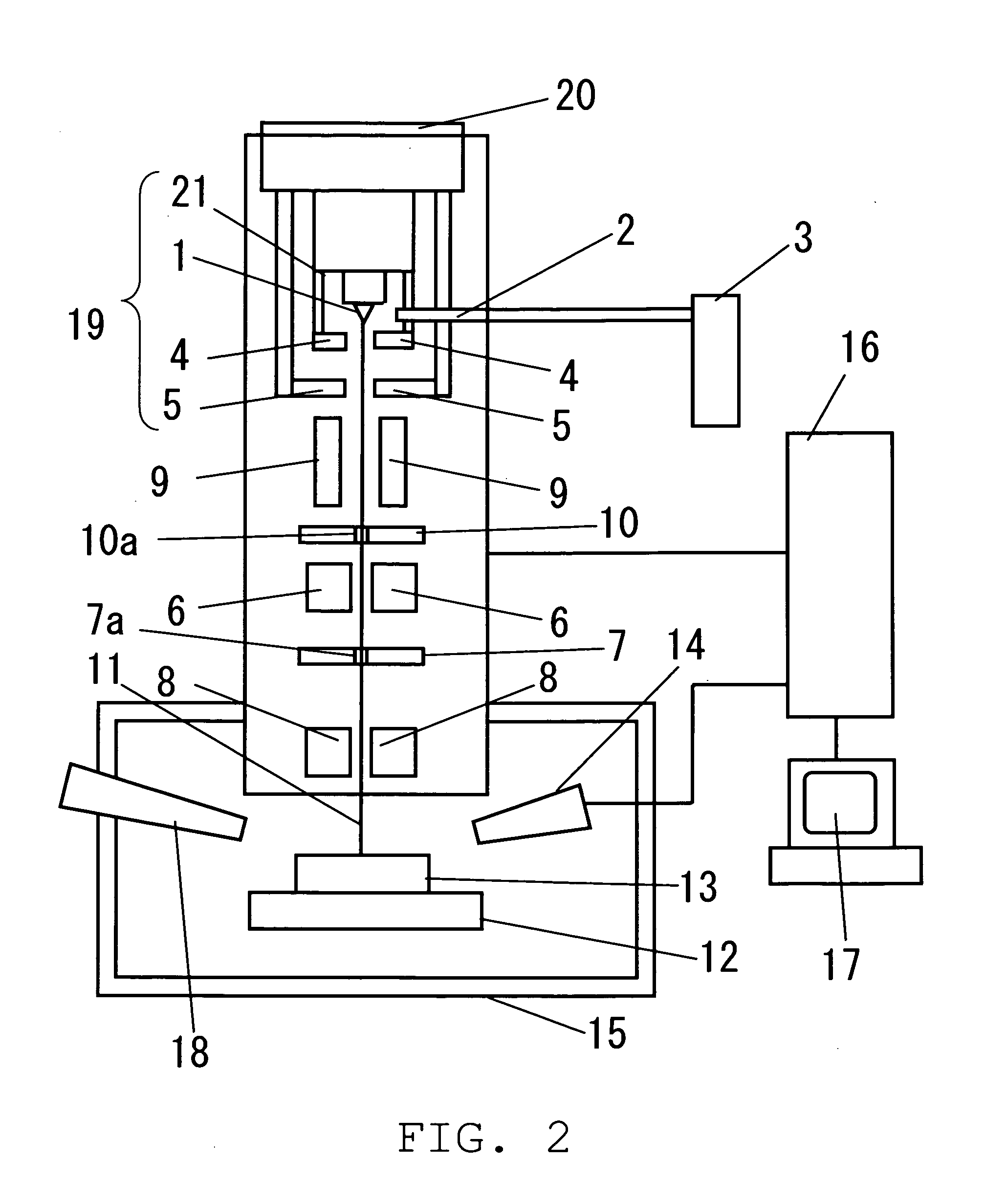
[0077]An observing and processing method according to the embodiment will be described. Helium gas is supplied to the tip 1 cooled by the cooling device 24 via the ion source gas nozzle 2 to cause the helium gas to adsorb onto the tip 1.

[0078]The helium gas adsorbed on the tip 1 is ionized by applying a voltage between the tip 1 and the extracting electrode 4, and the ion 11a is ejected toward the lens system from the opening of the extracting electrode 4.

[0079]The center portion of the ion beam 11 deflected in axis of irradiation by the gun alignment electrode 9 passes through the opening of the second aperture 10, and enters the center portion of the focusing lens. The surface of the sample 13 is irradiated with the ion beam 11 focused by the lens system.

[0080]The secondary electrons generated from the sample 13 are detected by the detector 14. The detector 14 used here is preferably a secondary electron detector when detecting the secondary electrons, and a secondary ion detector...


PUM


Abstract

A focused ion beam apparatus includes an ion gun unit having an emitter tip, a gas supply unit that supplies gas to the tip, and an ion source gas supply source. An extracting electrode ionizes the gas adsorbed onto the surface of the tip and extracts ions by applying a voltage between the extracting electrode and the tip. A cathode electrode accelerates the ions toward a sample. An aperture member has an opening that passes therethrough a part of the ion beam ejected from the ion gun unit, and a lens system focuses the ion beam onto the sample.

Description

BACKGROUND OF THE INVENTION[0001]1. Field of the Invention[0002]The present invention relates to a focused ion beam apparatus having a gas field ion source.[0003]2. Description of the Related Art[0004]In the related art, liquid metal gallium is employed as an ion source of a focused ion beam apparatus. In recent years, a focused ion beam apparatus employing a gas field ion source which is configured to supply an ion source gas to a fine tip, ionize the ion source gas adsorbed to the tip by a strong electric field formed at an extremity of the tip, and extract an ion beam is developed.[0005]In the ion source using the liquid metal gallium in the related art, an opening angle of the ion beam ejected from the ion source is on the order of 20 degrees. In contrast, in the gas field ion source, since the ion beam is ejected from several atoms at the extremity of the tip, the opening angle of the ion beam is on the order of several degrees.[0006]When using the gas field ion source, since t...

Claims


Application Information

Patent Timeline
Patent Type & Authority Applications(United States)
IPC IPC(8): H01J3/14
CPCH01J37/08H01J2237/0451H01J2237/0458H01J2237/31749H01J2237/083H01J2237/24535H01J2237/28H01J2237/0807
Inventor OGAWA, TAKASHINISHINAKA, KENICHIKOYAMA, YOSHIHIRO
Owner HITACHI HIGH TECH SCI CORP
Why Eureka
Try Eureka