
Hybrid in-situ dry cleaning of oxidized surface layers

Active Publication Date: 2011-09-01
TOKYO ELECTRON LTD
View PDF5 Cites 52 Cited by
  • Summary
  • Abstract
  • Description
  • Claims
  • Application Information

AI Technical Summary

Benefits of technology

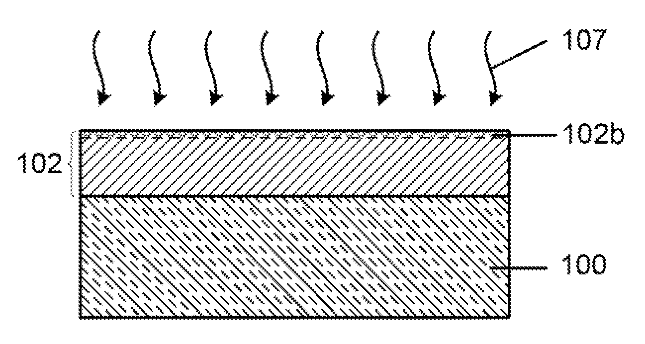
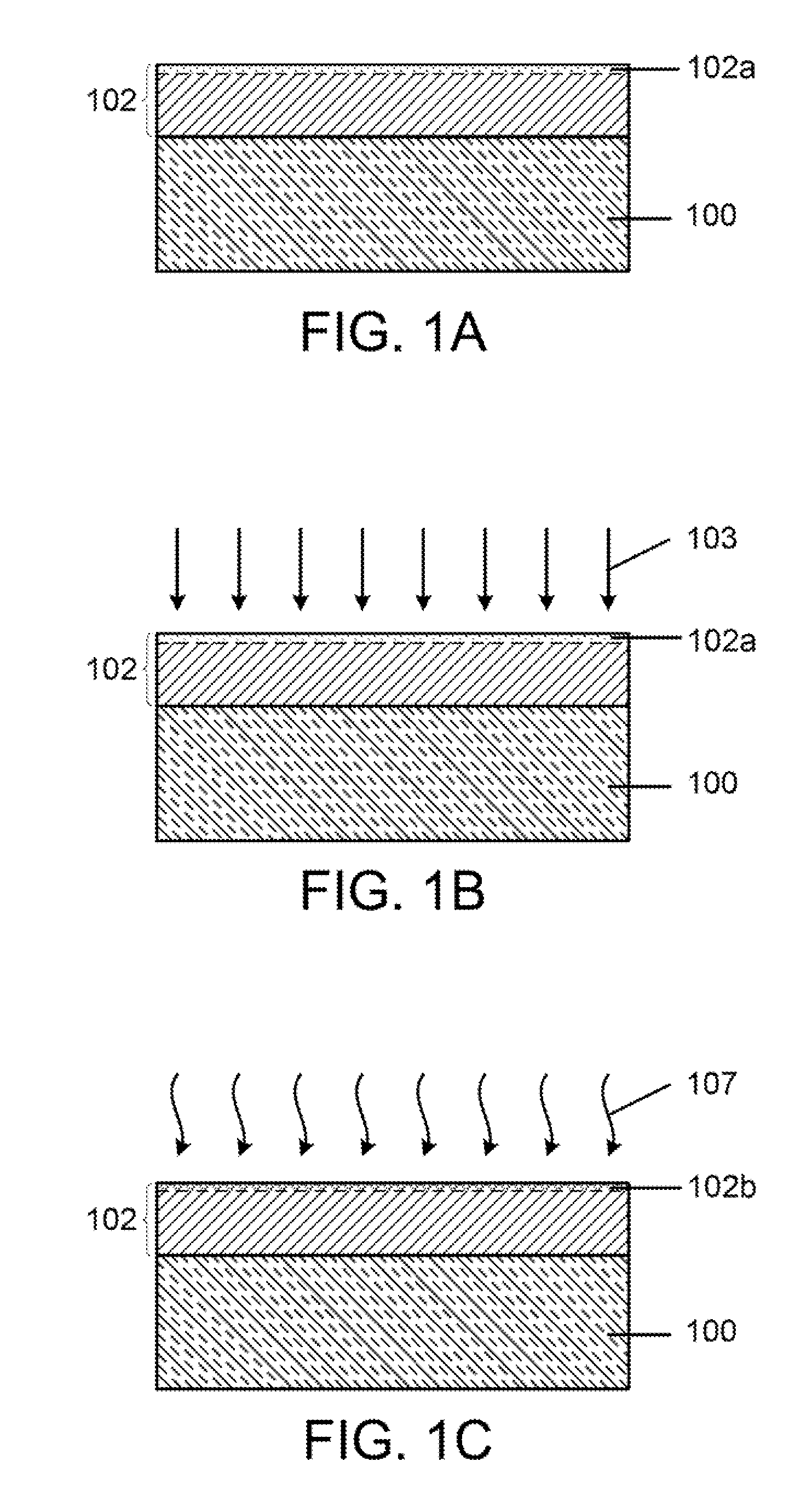
[0007]According to one embodiment, the method includes providing a substrate containing a metal-containing barrier layer having an oxidized surface layer, exposing the oxidized surface layer to a flow of a first process gas containing plasma-excited argon (Ar) gas to activate the oxidized surface layer and applying substrate bias power during the exposing of the oxidized surface layer to the flow of the first process gas. The method further includes exposing the activated oxidized surface layer to a second process gas containing non-plasma-excited hydrogen gas, where the exposure to the first process gas, in addition to activating the oxidized surface layer, facilitates chemical reduction of the activated oxidized surface layer by the second process gas containing the hydrogen gas. A thickness of the metal-containing barrier layer is not substantially changed by the exposing and applying steps.
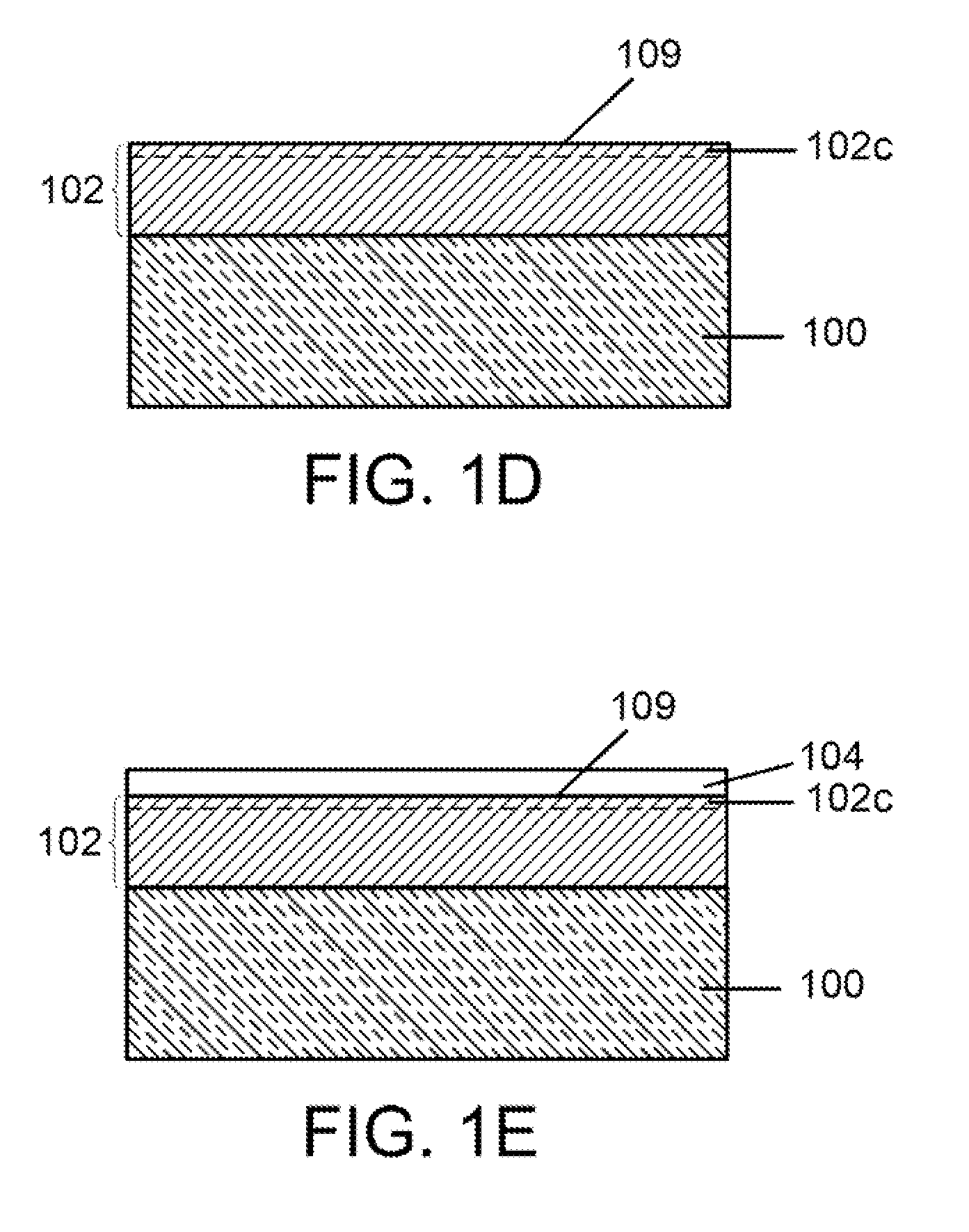
[0008]According to another embodiment, a method is provided for processing a substrate. The method includes providing the substrate in a vacuum processing tool, depositing a metal-containing barrier layer on the substrate in the vacuum processing tool, and performing a hybrid in-situ dry cleaning of an oxidized surface of the metal-containing barrier layer. The hybrid in-situ dry cleaning includes exposing the oxidized surface layer to a flow of a first process gas containing plasma-excited argon gas to activate the oxidized surface layer, applying substrate bias power during the exposing of the oxidized surface layer to the flow of the first process gas, and exposing the activated oxidized surface layer to a second process gas containing non-plasma-excited hydrogen gas, where the exposure to the first process gas, in addition to activating the oxidized surface layer, facilitates chemical reduction of the activated oxidized surface layer by the second process gas containing the hydrogen gas. A thickness of the metal-containing barrier layer is not substantially changed by the exposing and applying steps. The method still further includes following the performing, depositing a metal-containing film on the metal-containing barrier layer, wherein the hybrid in-situ dry cleaning and the depositing the metal-containing film on the metal-containing barrier layer are carried out without exposing the metal-containing barrier layer to air.
[0009]According to yet another embodiment, a method is provided for processing a substrate. The method includes providing the substrate in a first vacuum processing tool, depositing a metal-containing barrier layer on the substrate in the first vacuum processing tool, transferring in air the substrate containing the metal-containing barrier layer from the first vacuum processing tool to a second vacuum processing tool, and performing a hybrid in-situ dry cleaning of an oxidized surface of the metal-containing barrier layer in the second vacuum processing tool. The hybrid in-situ dry cleaning process includes exposing the oxidized surface layer to a flow of a first process gas containing plasma-excited argon gas to activate the oxidized surface layer, applying substrate bias power during the exposing of the oxidized surface layer to the flow of the first process gas, and exposing the activated oxidized surface layer to a second process gas containing non-plasma-excited hydrogen gas, wherein the exposure to the first process gas, in addition to activating the oxidized surface layer, facilitates chemical reduction of the activated oxidized surface layer by the second process gas containing the hydrogen gas. A thickness of the metal-containing barrier layer is not substantially changed by the exposing and applying steps. The method still further includes following the performing, depositing a metal-containing film on the metal-containing barrier layer in the second vacuum processing tool, wherein the hybrid in-situ dry cleaning and the depositing the metal-containing film on the metal-containing barrier layer are carried out without exposing the metal-containing barrier layer to air.

Problems solved by technology

The presence of impurities in the Ta-containing barrier layer can result in poor adhesion between the Ta-containing barrier layer and adjacent materials, including Cu metal layers.
The poor adhesion between the Ta-containing barrier layer and adjacent materials can result in electro-migration (EM) and stress migration (SM) problems in the integrated circuit, as well as reduced device production yields.
Therefore, even partial removal of a thickness of an ultra-thin diffusion barrier layer using common plasma etching processes is not acceptable.

Method used


Image

  • Hybrid in-situ dry cleaning of oxidized surface layers
  • Hybrid in-situ dry cleaning of oxidized surface layers
  • Hybrid in-situ dry cleaning of oxidized surface layers

Examples


Embodiment Construction

[0017]Methods for hybrid in-situ dry cleaning of oxidized surface layers are disclosed in several embodiments. However, one skilled in the relevant art will recognize that the various embodiments may be practiced without one or more of the specific details, or with other replacement and / or additional methods, materials, or components. In other instances, well-known structures, materials, or operations are not shown or described in detail to avoid obscuring aspects of various embodiments of the invention. Similarly, for purposes of explanation, specific numbers, materials, and configurations are set forth in order to provide a thorough understanding of the invention. Furthermore, it is understood that the various embodiments shown in the drawings are illustrative representations and are not necessarily drawn to scale.

[0018]Reference throughout this specification to “one embodiment” or “an embodiment” means that a particular feature, structure, material, or characteristic described in...


PUM

PropertyMeasurementUnit
Pressureaaaaaaaaaa
Poweraaaaaaaaaa
Poweraaaaaaaaaa

Abstract

According to one embodiment, the method includes providing a substrate containing a metal-containing barrier layer having an oxidized surface layer, exposing the oxidized surface layer to a flow of a first process gas containing plasma-excited argon gas to activate the oxidized surface layer and applying substrate bias power during the exposing of the oxidized surface layer to the flow of the first process gas. The method further includes exposing the activated oxidized surface layer to a second process gas containing non-plasma-excited hydrogen gas, wherein the exposure to the first process gas, in addition to activating the oxidized surface layer, facilitates chemical reduction of the activated oxidized surface layer by the second process gas containing the hydrogen gas. A thickness of the metal-containing barrier layer is not substantially changed by the hybrid in-situ dry cleaning process.

Description

FIELD OF INVENTION[0001]The present invention relates to a method of dry cleaning oxidized surface layers, and more particularly to a method of in-situ dry cleaning of oxidized barrier layers used in metallization of integrated circuits.BACKGROUND OF THE INVENTION[0002]The introduction of copper (Cu) metal into multilayer metallization schemes for manufacturing integrated circuits necessitates the use of barrier layers to promote adhesion and growth of the Cu layers and to prevent diffusion of Cu into dielectric materials, for example low dielectric constant (low-k) dielectric materials with k values below that of SiO2 (k˜3.9). Barrier layers that are deposited onto dielectric materials can include refractive materials, such as tungsten (W), molybdenum (Mo), and tantalum (Ta), and compounds thereof. These materials are non-reactive and immiscible in Cu, and can offer low electrical resistivity.[0003]Cu integration schemes for technology nodes less than or equal to 130 nm can utilize...

Claims


Application Information

Patent Timeline
IPC IPC(8): B05D3/10
CPCC23C14/5826H01L21/76862H01L21/76843H01L21/02068H01L21/302H01L21/3065
Inventor SELSLEY, ADAMCERIO, JR., FRANK M.
Owner TOKYO ELECTRON LTD
Learn More