Method and apparatus for feeding chemicals into a process liquid flow

a technology of process liquid and chemical feed, which is applied in the direction of chemical/physical processes, textiles and paper after-treatment, etc., can solve the problems of uneven product quality, poor success, and weak retention ability, and achieve the effects of reducing the efficiency of chemicals, and reducing the cost of production

Inactive Publication Date: 2011-09-22
WETEND TECH
View PDF6 Cites 6 Cited by
  • Summary
  • Abstract
  • Description
  • Claims
  • Application Information

AI Technical Summary

Benefits of technology

[0009]The retention takes place either as a mechanical or a chemical retention where the basic idea is to change the charge of the additional chemicals so that they would be adsorbed to the fiber as efficiently as possible. The charge changes while the process proceeds, which may cause dissolving of the flocks, which have already been formed and thus result in weakening of the efficiency of the chemical and thus overdosing. Thus, if the feeding of the retention chemical to the paper pulp could be optimized so that the chemical in question would be introduced in a location as close to the headbox as possible, considerable savings could be made in chemical costs.
[0013]Sizing agents, examples of which are ASA (alkenylsuccinic anhydride=alkylene amber acid anhydride) and AKD (alkylketene dimer) are substances designed to prevent water from being absorbed to the paper. They are usually employed when producing paper in neutral or alkaline conditions. The main aims in using ASA are preventing the reactions (hydrolysis) taking place with water, even distribution and mixing of ASA into the paper pulp, and efficient retention to the product to be produce. The hydrolysis is prevented by preparing the ASA emulsion only as late as possible before the emulsion is mixed to the paper pulp. The pH of the cationic starch solution, which is used in preparing the emulsion, is decreased for example with alum. The purpose of the starch solution is to coat the ASA droplets so that they would not at once contact water. Prior art suggests adding the ASA emulsion at a position after the vortex cleaner in the short circulation, in other words the region preceding degassing and the headbox feed pump. Although the cationic starch coating around the ASA droplets to some extent contributes to the attaching of the sizing agent to the fibers, an efficient retention system is still needed to retain the sizing agent quickly in the web to be produced. Immediate retention is important as the sizing agent is in any case bound to the fines and filler and if it does not retain in the web, it ends up in the water circulations and becomes hydrolysed. Hydrolyzed ASA in turn can cause flocks, running problems and deterioration of sizing.
[0015]AKD is brought to the mill as a milky emulsion, whereby its use is fairly easy. As the reactivity of AKD is weaker compared to ASA, its use is also more flexible. Many paper manufacturers add AKD to high consistency pulp, in other words before dilution of the pulp to a consistency suitable for the headbox. In this way the AKD is brought to the surface of the fibers. On the other hand, if AKD is dosed to a pulp in a consistency suitable for the headbox it is justified to assume that it adheres mostly to the fines. If PCC is present it can decrease the efficiency of the sizing agent and also with time reduce the effect of the sizing for example during storage.
[0021]Several different prior art methods and apparatus are known for feeding both retention chemicals and among other things the additives described above to the paper pulp. According to the conventional paper stock manufacturing method, both the various paper pulp fiber fractions and the additives, fillers, sizing agents etc. required in the paper manufacture are brought to a mixing tank in the so-called short circulation. Also a part of the retention chemical / chemicals has / have conventionally been introduced to the mixing tank. In the mixing tank, as also the name suggests, the paper pulp is efficiently mixed so that both the different fibers and the various additives are mixed homogenously and the consistency of the suspension formed of these is adjusted to a desirable level. From the mixing tank the paper pulp is pumped by means of the headbox feed pump towards the head box in most cases via vortex cleaning, gas separation and a headbox screen or the so-called machine screen. Both the feed pump in question and the headbox screen mix the pulp further, in other words they keep the paper pulp as homogenous as possible. A retention chemical is fed to the paper pulp after the headbox screen with the intention to ensure the retention of a certain or some additive(s), filler(s) or sizing agent(s) of the paper pulp in the paper machine wire section.
[0027]The method and system disclosed herein may be applied, for example, to solve the following problems: hydrolysis of different chemicals due to too early mixing; change of the electrical properties of the retention chemicals due to too early mixing; high investment costs; a mixer of its own for each chemical; each mixer to a different location in the short circulation; large apparatus; powerful electric motors; high operating costs caused by the powerful electric motors; high installation costs; constructing the stands; cutting the headbox feed duct; electrical installations required by the drive motor of the mixer, among other things in order to overcome the drawbacks described above the method and apparatus to be described below has been developed, the characteristic features of which are disclosed in the appended patent claims.
[0031]Embodiments of the method and the apparatus of the invention disclosed herein may provide among other things for example the following advantages: efficient and homogenous mixing of additive to the paper pulp; quick mixing of additive and retention chemical to each other; an essentially improved additive retention; reduced investment, installation and operation costs, and lower chemical costs, only to mention a few advantages.

Problems solved by technology

If efforts are made to cause these additives / fillers to remain in the paper to be produced, the success is poor as the fibers having the same electric charge reject these additives / fillers.
Performed tests have further shown that the longer the retention chemical is in contact with for example the fibers the weaker its retention ability becomes.
For example an excessive dose of the retention chemical results in flocks in the end product, which are seen as uneven quality of the product.
ASA, which is not retained in the fibers, is hydrolyzed during the process and the hydrolyzed ASA is detrimental to sizing and causes agglomeration in the process.
Thus, a common and often encountered problem with retention chemicals is the hydrolysis, where the chemicals in question react with water and loose their effect at a rate typical of each chemical.
The charge changes while the process proceeds, which may cause dissolving of the flocks, which have already been formed and thus result in weakening of the efficiency of the chemical and thus overdosing.
Hydrolyzed ASA in turn can cause flocks, running problems and deterioration of sizing.
If PCC is present it can decrease the efficiency of the sizing agent and also with time reduce the effect of the sizing for example during storage.
The worst known problem associated with the retention chemicals has until now been the fact that it has not been possible to mix them in an adequately homogenous and quick way to the paper pulp.
This has, however, had the consequence that on the other hand the retention chemical has lost some of its efficiency for example for the reasons associated with the evening out of the electric charges and chemical phenomena mentioned above and, on the other hand, due to the overdose, there have sometimes been complaints about the quality of the end product.
It must be stated, however, that the long mixing time and the mixing distance provided for evening out the mixing which reduces the efficiency of the retention chemical has to some extent compensated the chemical overdose whereby the drawbacks have not been so imminent.
Then there is, however, the danger that even a remarkable portion of the retention chemical is not retained in the web but becomes hydrolyzed and ends up with the filtrate of the wire section in the short circulation where it may for example cause precipitation.
Further, it has been explained above how in connection with the feeding of an additive it has been found detrimental to feed the retention chemical to the paper pulp at a very early stage compared with the feeding of the additives.
Feeding a small volume to a large volume homogenously is not successful if as efficient mixing as possible is not guaranteed at the feeding moment.
A very weak additive retention has been found to be a problem in the prior art short circulation process.
Additives can also be different in reactivity and thus they can for example be hydrolyzed and precipitated at a point in the process, which results both in an additive loss and problems in the process both because of fouling and detaching of the deposits, which takes place from time to time.
There are, however, a few drawbacks in the use of this apparatus.
A mechanical mixer still has other weaknesses.
These are for example the high price and the high operating costs because a mixer capable of mixing the chemicals homogenously over the whole diameter of the headbox feed pipe is large and it consumes a huge amount of energy while performing the mixing action.
Further, the installation of the mechanical mixer to the pipelines and the drive motor on a stand of its own and constructing the electrical connections required involves a lot of work and supplies.
According to our understanding, however, the practice has shown that the turbulence created by the contoured members is in most cases too weak to mix the chemicals homogenously to the paper pulp flow.
The reason can be for example that it is not possible to provide in a sensible way in the headbox feed duct a duct section containing the turbulence elements that would be long enough.
Further problems may be the flow resistance caused by the turbulence elements, which changes the power requirement of the headbox feed pump and possibly the local pressure fluctuations caused by the elements, which can be reflected up to the headbox.

Method used


Image

  • Method and apparatus for feeding chemicals into a process liquid flow
  • Method and apparatus for feeding chemicals into a process liquid flow
  • Method and apparatus for feeding chemicals into a process liquid flow

Examples


Embodiment Construction

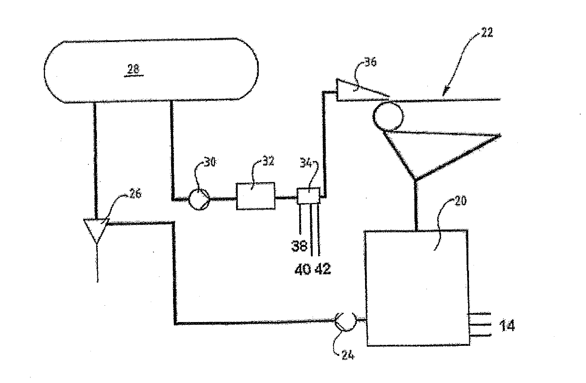
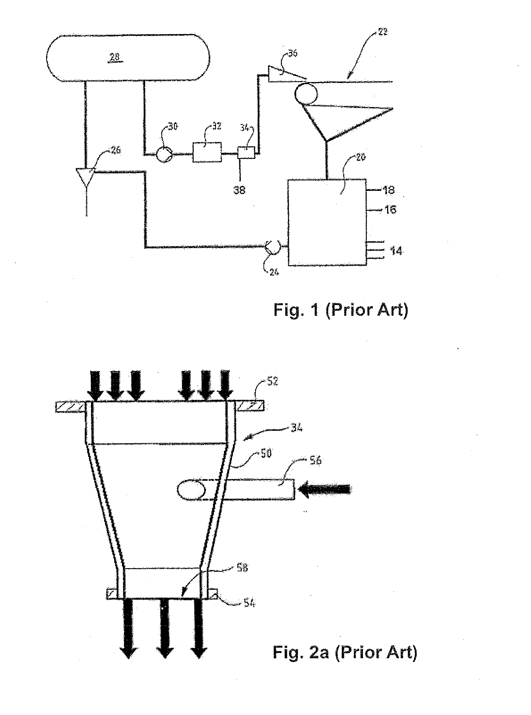
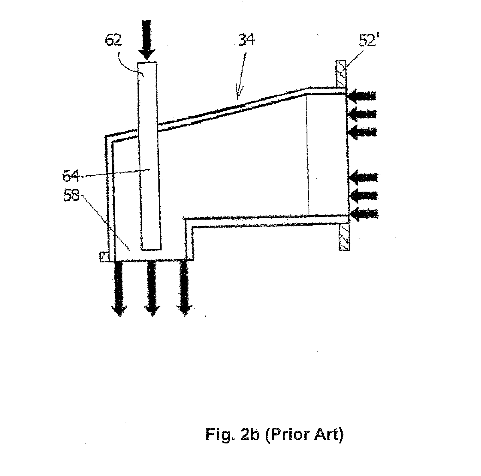
[0038]According to FIG. 1, the prior art short circulation process arrangement works so that paper pulp to be fed to a paper machine, which is generally illustrated by a wire section 22, is diluted to the applicable consistency in a wire pit 20 with white water from the paper machine 22, although a separate mixing tank may also be utilized. Other suitable liquids may be used for dilution too, if desired, as for instance filtrate from a white water filter. Thus, both various fiber fractions 14, which the paper to be manufactured is desired to contain and various additives and filler 16, the use of which both saves valuable fibers and gives the paper desired properties such as for example brightness / opacity, gloss, moisture resistance, etc are brought to the wire pit 20. All these and possibly also at least a portion 18 of the retention chemicals are mixed in the wire pit with a mixer suitable for that purpose, to form a homogenous suspension. From the wire pit 20, the fiber suspensio...


PUM

PropertyMeasurementUnit
timeaaaaaaaaaa
distanceaaaaaaaaaa
homogenousaaaaaaaaaa

Abstract

A method of mixing at least two chemicals or additives into a process liquid flow flowing in a process liquid flow duct including: feeding a liquid jet to the process liquid flow in the process liquid flow duct, wherein the liquid jet is formed in a feeding device and the liquid jet flows in a transverse direction to a flow direction of the process liquid flow through the process liquid flow duct; mixing the at least two chemicals or additives together to form a mixture; feeding the mixture of the at least two chemicals or additives into the process liquid flow duct with the feeding liquid jet, and mixing the at least two chemicals or additives with the feeding liquid jet in the process liquid flow duct.

Description

RELATED APPLICATION[0001]This invention is a divisional application of Ser. No. 11 / 572,165, filed 29 Oct. 2007, which is the US national phase of international application PCT / FI2005 / 000329 filed 12 Jul. 2005 which designated the U.S. and claims benefit of Finnish Application No. 20040990 filed 16 Jul. 2004, the entire contents of all of these applications are incorporated by reference.SUMMARY OF BACKGROUND AND INVENTION[0002]A method and an apparatus for feeding chemicals into a process liquid flow are disclosed herein. An application of a preferred embodiment of the method and the apparatus of the present invention is feeding retention chemical / chemicals together with an additive, which may be another chemical or for example a mineral, to paper pulp suspension flow to be fed to a paper machine. The method and the apparatus of the invention are particularly well applicable in feeding an additive of the paper manufacture, such as filler, together with a retention chemical, to paper ...

Claims


Application Information

Patent Timeline
Patent Type & Authority Applications(United States)
IPC IPC(8): D21H23/00D21H17/67D21H17/33D21H17/68D21H17/66D21H17/52D21H17/37D21H17/29B01F3/08B01F5/00B01F5/02B01F5/04B01F15/02D21HD21H21/10D21H21/16D21H21/30D21H23/02D21H23/04
CPCB01F3/0865B01F5/0057B01F5/0405B01F5/045B01F5/0471D21H23/02B01F2215/0078D21H17/67D21H21/10D21H21/16D21H21/30B01F2015/0221B01F23/451B01F25/10B01F25/311B01F25/313B01F25/314B01F35/715B01F2101/47B01F25/20B01F35/71
Inventor MATULA, JOUNI
Owner WETEND TECH
Why Eureka
Try Eureka