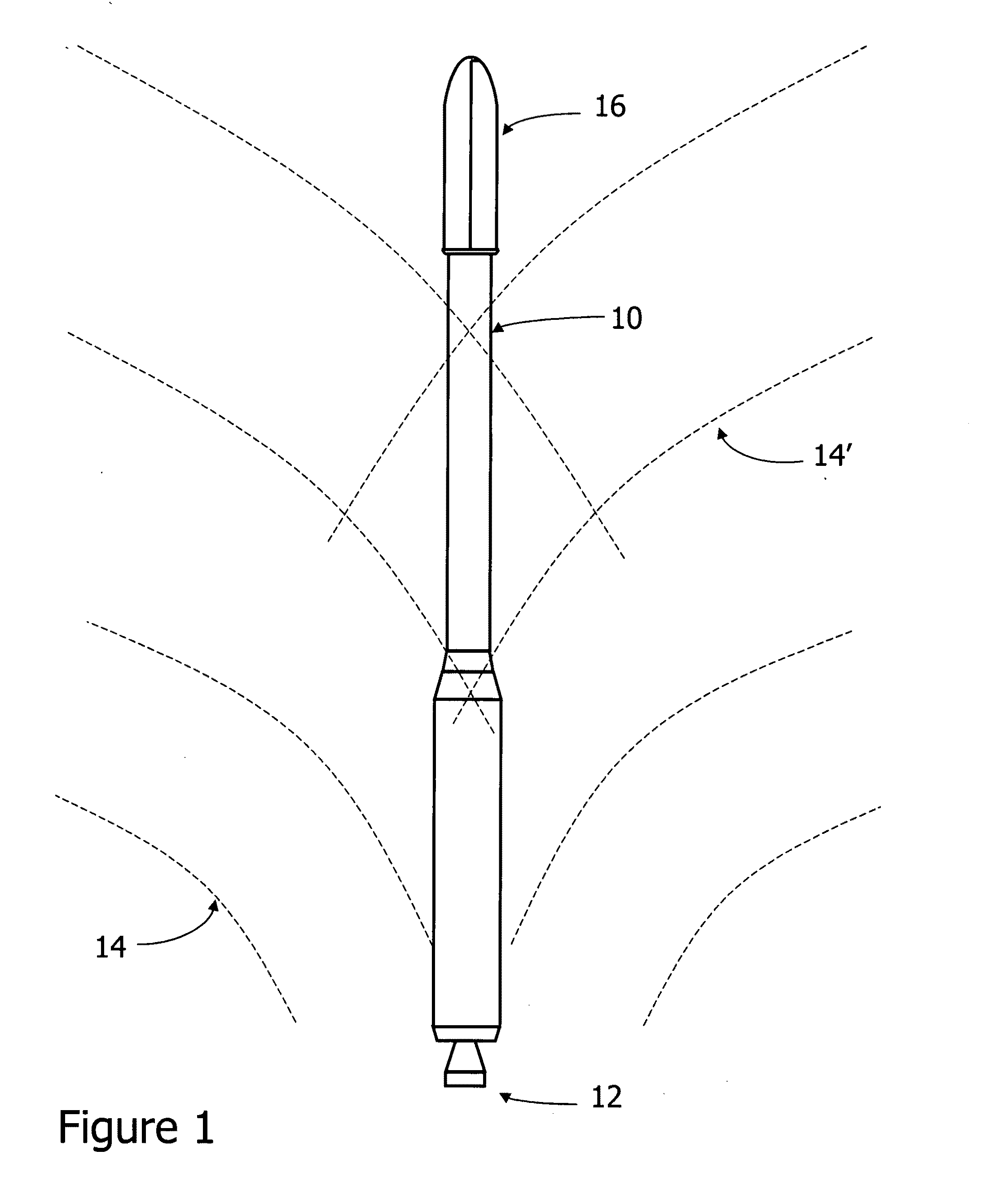
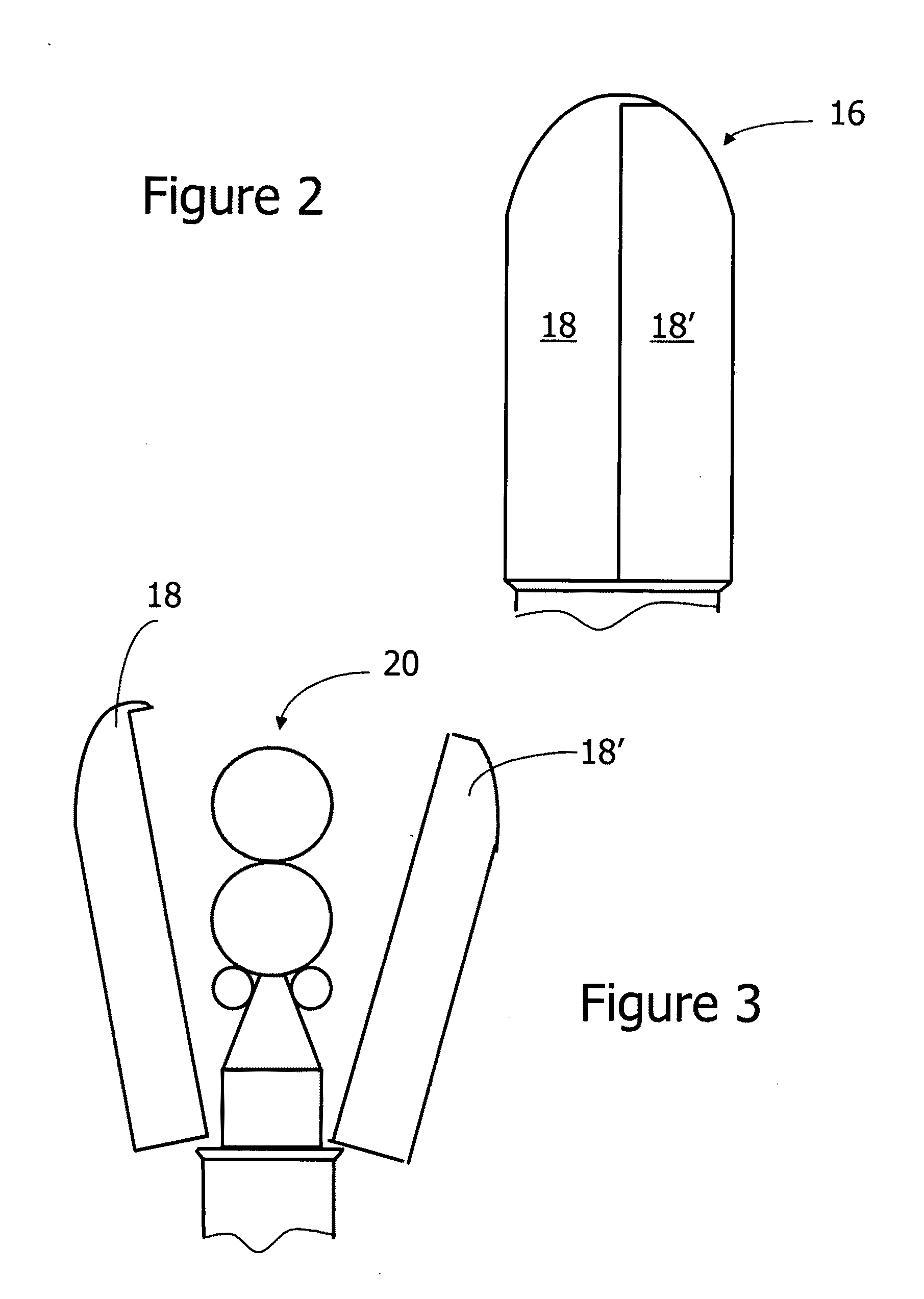
[0041]FIG. 2 is a perspective view, enlarged from that of FIG. 1, showing the fairing structure 16 portion of the launch vehicle 10, and FIG. 3 is a perspective view, enlarged from that of FIG. 1, showing the fairing structure portion 16 of the launch vehicle being jettisoned as two component panels, 18 and 18′ both of complex curvature, revealing a payload 20. FIG. 4 is a perspective cross sectional view taken along line 4-4 in FIG. 2 is a perspective view showing the interior configuration of the fairing structure 16 in a hoop direction, i.e., the direction around the circumference of the assembled fairing and perpendicular to the direction of acceleration of the vehicle 10. The stiffness of a structure of this shape will naturally have
high stiffness in the hoop direction. It is an
advantage of the invention that stiffness in the longitudinal direction is better than can be achieved with
honeycomb materials of similar weight and dimension.
[0042]The light-weight acoustic dampening launch vehicle fairing structure has a high strength and stiffness and
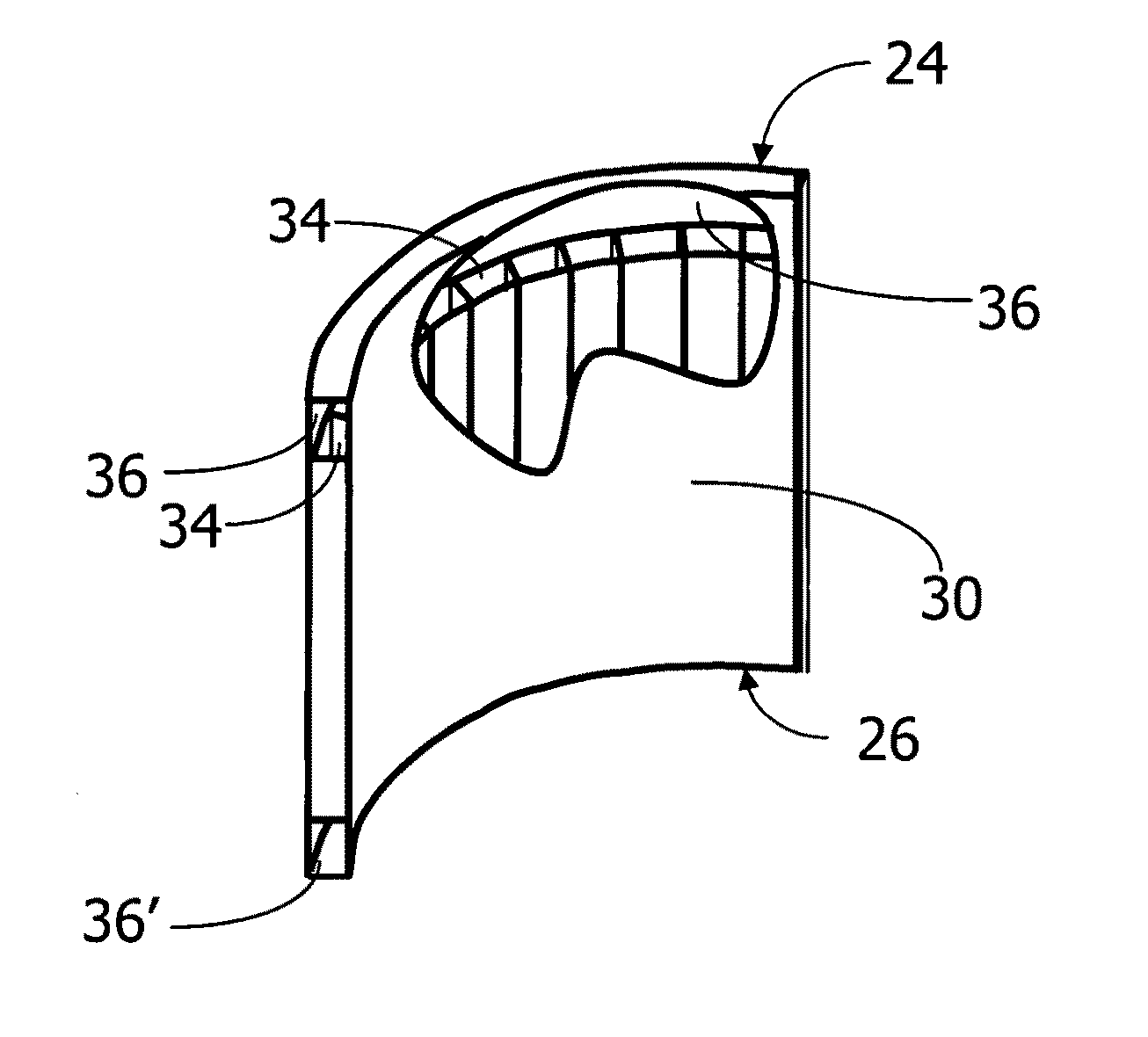
low mass density. The structure comprises a monolithic body 22 having a top 24 and a bottom 26, a inboard surface 28, an outboard surface 30 on the exterior of a central core 32 comprised of fibrous reinforcement material in a polymeric binder defining longitudinal chambers 34 extending from the top 24 to the bottom 26 of the monolithic body 22. Fluid passage means 36 and 36′ are provided for the longitudinal chambers 34 at both the top and bottom of the monolithic body to enable filling and emptying said chambers with a fluid. FIG. 5 shows one half of a fairing structure of FIG. 4, with a section
cut away along line 5-5 in FIG. 4, to show the internal structure including one of the longitudinal chambers 34 extended in the direction parallel with acceleration of the vehicle 10. The fluid passage means 36 and 36′ are shown as integral circumferential manifolds for filling and draining of the longitudinal tubes 34, but can be holes
cut following molding body 22. In either or other form, they can be formed during molding or they can comprise mechanical fittings (not shown) supplied before or after molding. External fill valves of any effective form will be provided on means 36 and external drain valves on means 36′, but are not shown in this view for
clarity. The drain valves will be provided with
actuator means of known type to allow the water to be released in flight, such as a pyrotechnic valve or burst disk.
[0043]The terms “inboard surface” and “outboard surface” are chosen for convenience in describing what are shown in the drawings as opposed spaced surfaces. The terms “inboard” and “outboard” in this description can be viewed as describing, in the case of a
satellite payload fairing, the outer and inner surfaces, respectively. Thus, as shown, the inboard surface 28 has a compound convex curvature of the type useful for this application, and the outboard surface 30 is illustrated as being concave. Outside of this context, the terms can be reversed in terms of what is the exterior surface of a finished panel in use and what is the on the opposite side of it.
[0044]FIGS. 4, 5 and 6 schematically represent one form of panel 22 for forming the fairings 16 of the invention. In this case it is shaped for use in forming a fairing for protecting a rocket-launched payload from acoustic stress. The panel 22 of the invention is of monolithic structure and eliminates the use of
honeycomb structures as core and strength elements with the unexpected findings that acoustic protection is not diminished, significant strength to weight ratio improvements are achieved and the panels can be more quickly emptied, thus eliminating a payload weight penalty for carrying water or other shielding
mass longer than is necessary. In addition, the ability to form fairings without the need for honeycombs facilitates the formation of compound curvatures, such as the complex curves of FIG. 6, frequently required for aerodynamic effect. The invention enables achieving the compound curvatures without sacrificing strength or aesthetics or adding weight.
[0045]The longitudinal chambers 34 are preferably free of internal obstructions and provide an efficient path for a fluid, such as water or the like, to be filled into the chambers 34 and exhausted from them. Fluid passage means 36 at the top and similar fluid passage means 36′ at the bottom of the monolithic body 22 are interconnected by the longitudinal chambers 34 for filling and emptying said chambers 34 with a fluid. The provision of a monolithic structure with unobstructed longitudinal chambers 34 extending the length of the panel, from top to bottom, provides an improved manner to provide mass to help absorb physical stresses such as of
impact or
acoustic energy. As noted above, the chambers 34 can be and are preferably filled with a fluid to add mass. By the term fluid we mean a material which flows under its own weight or under moderate applied pressure. It can be a liquid or a flowable
solid, such as sand, or the like. Typically, the fluid will be a liquid material and will have a
viscosity suitable for the intended use, with viscosities within the range of from about 0.5 to about 20 centipoise, as measured at 25° C., being most typical. Lower viscosities are preferred to facilitate filling and draining, however the
acoustic attenuation properties of the fluid must also be considered. Water, aqueous mineral slurries, non aqueous slurries, and the like can be employed. They can be Newtonian, dilatent or pseudoplastic as the situation calls for.
[0046]FIG. 5 shows fluid passage means 36 and 36′ at both the top 24 and bottom 26 of the monolithic body 22 and interconnected by the longitudinal chambers 34 for filling and emptying said chambers with a fluid. By the terms “top” and “bottom” as used in this description, we are referring to the general orientation of the structures of the invention as shown in the drawings, wherein a fluid is introduced from the top and flows by gravity out of the bottom in an earth based
system without the use of any pumping or other flow inducing added forces. However, for rockets at launch the g forces on the device may effectively be at an orientation of less than vertical, with the term “top” still referring to an inlet end or edge and the term “bottom” still referring to an outlet end or edge.


