Supercharge Your Innovation With Domain-Expert AI Agents!

Semiconductor substrate, electronic device and method for manufacturing semiconductor substrate

a semiconductor substrate and electronic device technology, applied in the direction of semiconductor devices, basic electric elements, electrical appliances, etc., can solve the problems of instable operation of semiconductor devices and further decrease of resistivity, and achieve high resistance, high resistance, and high resistance layer

Inactive Publication Date: 2011-09-22
SUMITOMO CHEM CO LTD
View PDF3 Cites 0 Cited by
  • Summary
  • Abstract
  • Description
  • Claims
  • Application Information

AI Technical Summary

Benefits of technology

[0006]For a solution to the above-mentioned problems, according to the first aspect related to the present invention, provided is one exemplary semiconductor wafer including: a base wafer; a seed crystal disposed on the base wafer; a compound semiconductor disposed above the seed crystal; and a high resistance layer disposed between the seed crystal and the compound semiconductor, the high resistance layer having a larger resistivity than the seed crystal, where the seed crystal lattice matches or pseudo lattice matches the compound semiconductor. For example, the lattice spacing of the compound semiconductor in the direction parallel to the main plane of the base wafer is substantially equal to the lattice spacing of the seed crystal in the direction parallel to the main plane. In addition, the high resistance layer lattice can match or pseudo lattice match the seed crystal, and the compound semiconductor lattice can match or pseudo lattice match the high resistance layer. For example, the base wafer is a Si wafer, a SOI wafer, or a GOI wafer.

Problems solved by technology

In addition, since the constituting component of GaAs and the constituting component of a germanium-silicon alloy are electrically active impurities in relation to each other, doping occurs by interdiffusion of these components, which tends to further decrease the resistivity.
As a result of decrease in resistivity of the germanium-silicon alloy layer, insulation between GaAs and the silicon wafer may become insufficient, which leads to instable operation of the semiconductor device in some cases.

Method used


Image

  • Semiconductor substrate, electronic device and method for manufacturing semiconductor substrate
  • Semiconductor substrate, electronic device and method for manufacturing semiconductor substrate
  • Semiconductor substrate, electronic device and method for manufacturing semiconductor substrate

Examples


embodiment examples

Embodiment Example 1

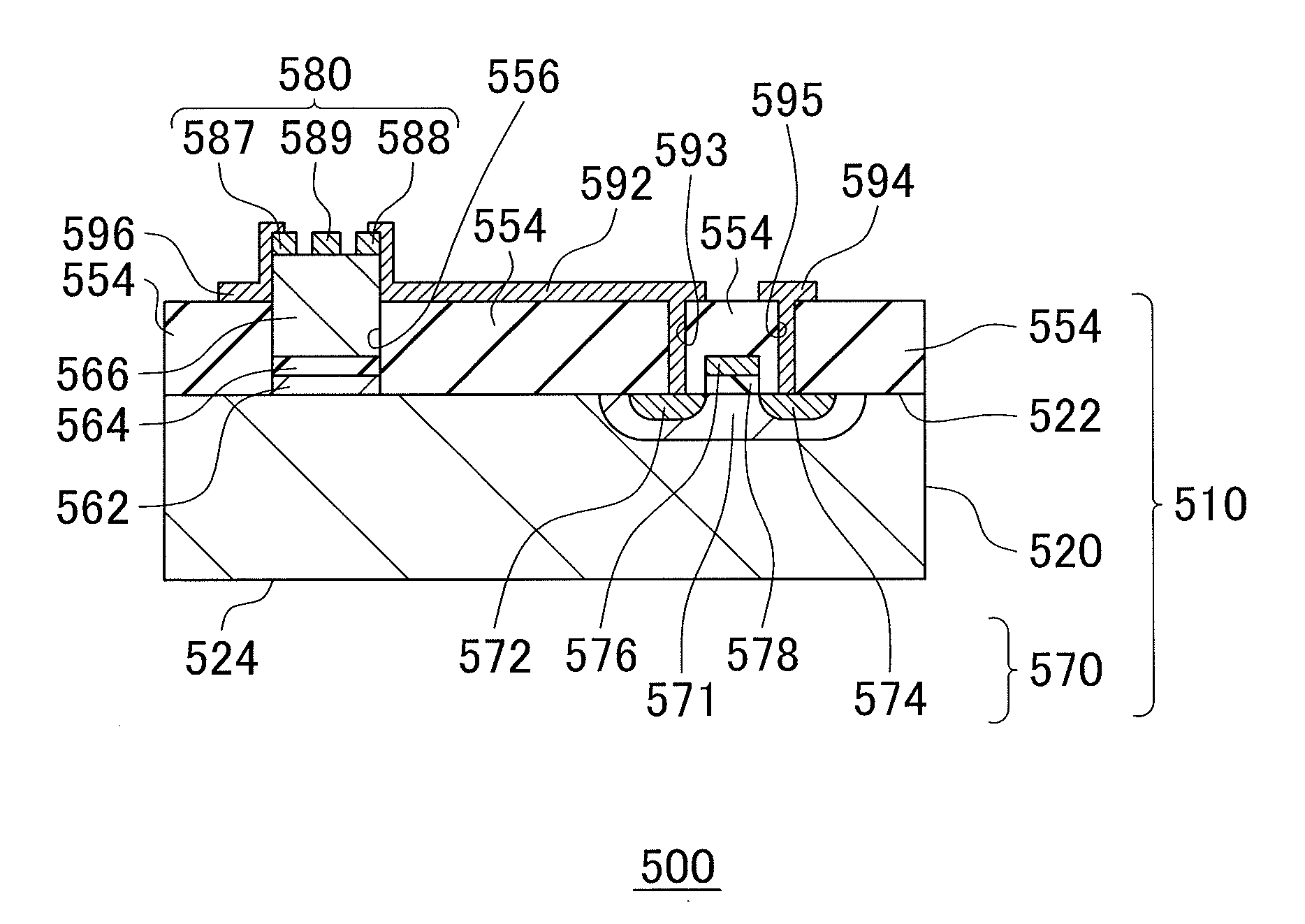
[0106]An electronic device 500 was fabricated according to the procedure shown in FIG. 6. A commercially-available SOI wafer was prepared as the base wafer 520. As a first electronic element 570, a MOSFET was formed on the Si crystal layer of the base wafer 520. The wafer 710 was prepared in this way. As an inhibition layer 554, a SiO2 layer was formed by CVD to be in contact with the first main plane 522 of the base wafer 520. The average thickness of the SiO2 layer was 1 μm. An opening 556 was formed through a part of the inhibition layer 554 by lithography. The size of the opening 556 was set to be 15 μm×15 μm.

[0107]Thus formed wafer 710 was placed inside the reaction chamber, and a Ge crystal layer was formed as a seed crystal 562. The Ge crystal layer was selectively formed inside the opening 556 by CVD. The Ge crystal layer is formed by first depositing about 20 nm under a condition of the source gas being GeH4, the pressure in the reaction chamber being 2....

embodiment example 2

[0114]A semiconductor wafer 510 was fabricated just as in Embodiment Example 1, except that an AlGaAs layer that has an Al composition of 0.3 with respect to the total of Al and Ga and that includes oxygen in an atomic concentration of about 5×10¹⁹ / cm3 was used as the high resistance layer 564, instead of using the selectively oxidized AlGaAs layer. Dibutyl ether was used as the oxygen source. The dibutyl ether was obtained by adding, to the source gas, hydrogen aerated through the dibutyl ether liquid maintained to 25 degrees centigrade in a flow rate of 200 cc / minute, and supplied during the crystal growth of the AlGaAs layer. The above-described oxygen concentration was achieved in this method. The other procedures are the same as adopted in Embodiment Example 1.

[0115]The leak current between the collector electrodes in the plurality of HBTs respectively formed in the openings adjacent to each other was observed to be extremely low (1.3×10⁻⁸A on average for 10V applied voltage). ...

embodiment example 3

[0116]A semiconductor wafer 510 was fabricated just as in Embodiment Example 1, except that an InGaP layer that includes boron in an atomic concentration of about 2×10²⁰ / cm3 was used as the high resistance layer 564, instead of using the selectively oxidized AlGaAs layer. Trimethyl boron was used as the boron source. The trimethyl boron was obtained by adding, to the source gas, hydrogen aerated through the trimethyl boron liquid maintained to 10 degrees centigrade in a flow rate of 1 cc / minute, and supplied during the crystal growth of the InGaP layer. The above-described boron concentration was achieved in this method. The other procedures are the same as adopted in Embodiment Example 1.

[0117]The leak current between the collector electrodes in the plurality of HBTs respectively formed in the openings adjacent to each other was observed to be extremely low (2.7×10⁻⁹A on average for 10V applied voltage). As clear from the above, obtained are a semiconductor wafer and an electronic ...


PUM


Abstract

A semiconductor wafer including: a base wafer; a seed crystal disposed on the base wafer; a compound semiconductor disposed above the seed crystal; and a high resistance layer disposed between the seed crystal and the compound semiconductor, the high resistance layer having a larger resistivity than the seed crystal, and the seed crystal lattice matching or pseudo lattice matching the compound semiconductor is provided.

Description

TECHNICAL FIELD[0001]The present invention relates to a semiconductor wafer, an electronic device, and a method of manufacturing a semiconductor wafer.BACKGROUND ART[0002]Recently, various types of high-function electronic devices using a compound semiconductor such as GaAs in an active region have been developed. Crystallinity of the compound semiconductor has a great impact on the performance of the electronic device, and so it is required to form a compound semiconductor having superior crystallinity. For example, Patent Document 1 discloses a semiconductor device including GaAs having a low defect density grown on the silicon wafer.[0003]In Patent Document 1, a silicon oxide layer is formed on a silicon wafer, and a germanium-silicon alloy is formed inside an opening having been disposed in the silicon oxide layer. As a result, a germanium plane having an extremely small dislocation defect density is formed on the germanium-silicon alloy. GaAs grown on the germanium plane has a ...

Claims


Application Information

Patent Timeline
Patent Type & Authority Applications(United States)
IPC IPC(8): H01L29/12H01L21/20
CPCH01L21/02381H01L21/0245H01L21/02463H01L21/8258H01L21/02546H01L21/02636H01L21/02543H01L21/20
Inventor YAMANAKA, SADANORIHATA, MASAHIKOTAKADA, TOMOYUKI
Owner SUMITOMO CHEM CO LTD
Features
  • R&D
  • Intellectual Property
  • Life Sciences
  • Materials
  • Tech Scout
  • Unparalleled Data Quality
  • Higher Quality Content
  • 60% Fewer Hallucinations
Learn More