
Modular Charging System for Multi-Cell Series-Connected Battery Packs

a charging system and battery pack technology, applied in battery data exchange, charging and exchanging data chargers, transportation and packaging, etc., can solve problems such as hazardous conditions, large under-charged entire packs, and problems such as rapid mass production, to achieve favorable economies of scale and easy mass production

Inactive Publication Date: 2011-09-29
PALATOV POWER SYST
View PDF3 Cites 41 Cited by
  • Summary
  • Abstract
  • Description
  • Claims
  • Application Information

AI Technical Summary

Benefits of technology

[0008]A primary objective of the present invention is to provide a charging system for series-connected battery packs that optimizes charging individually for each cell in the pack without wasting energy in resistive shunts, and is readily scalable to any desired pack voltage. A second objective is to provide a charging system that reduces signal interconnect requirements for a pack, is mass-producible, reliable and cost effective.
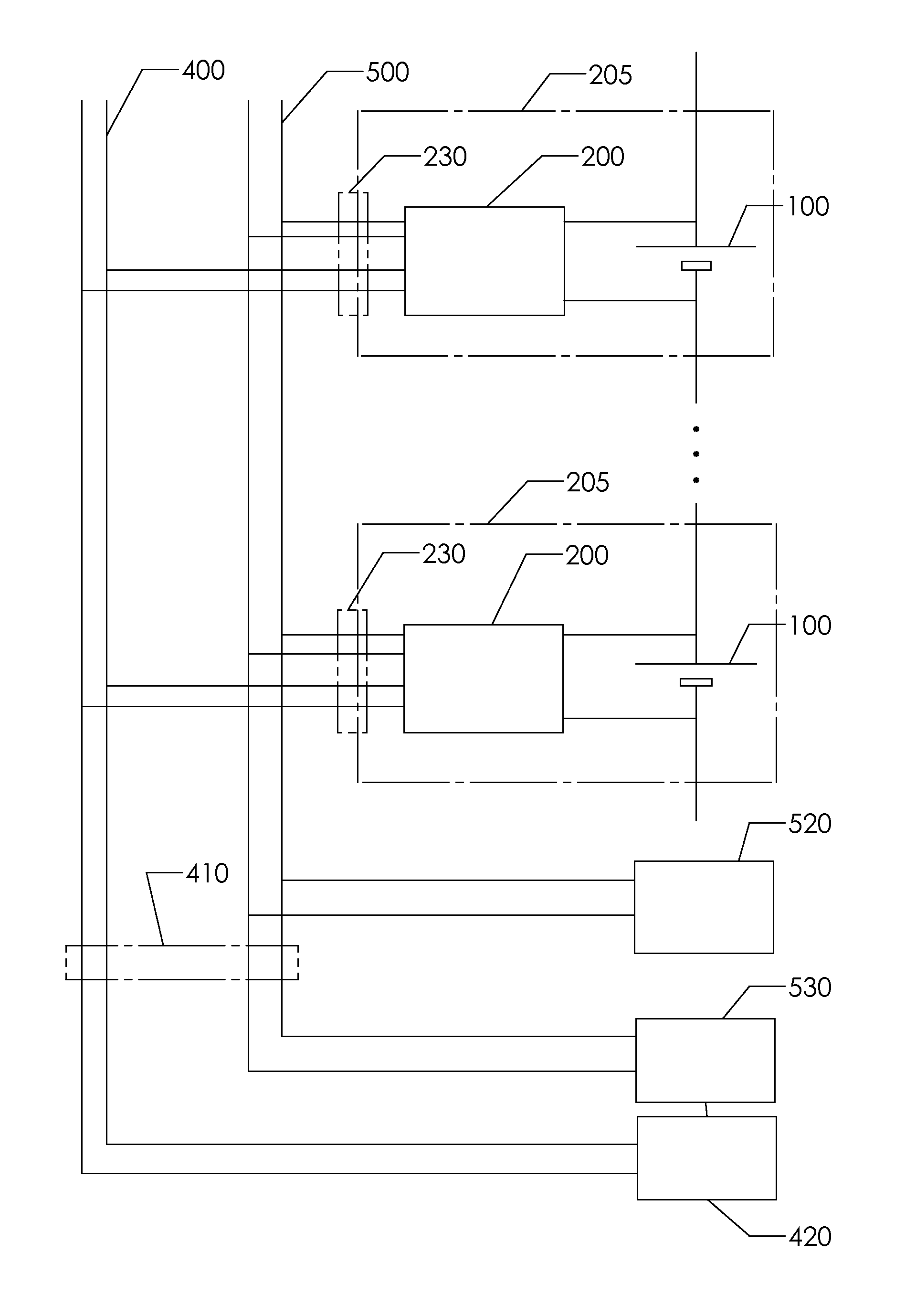
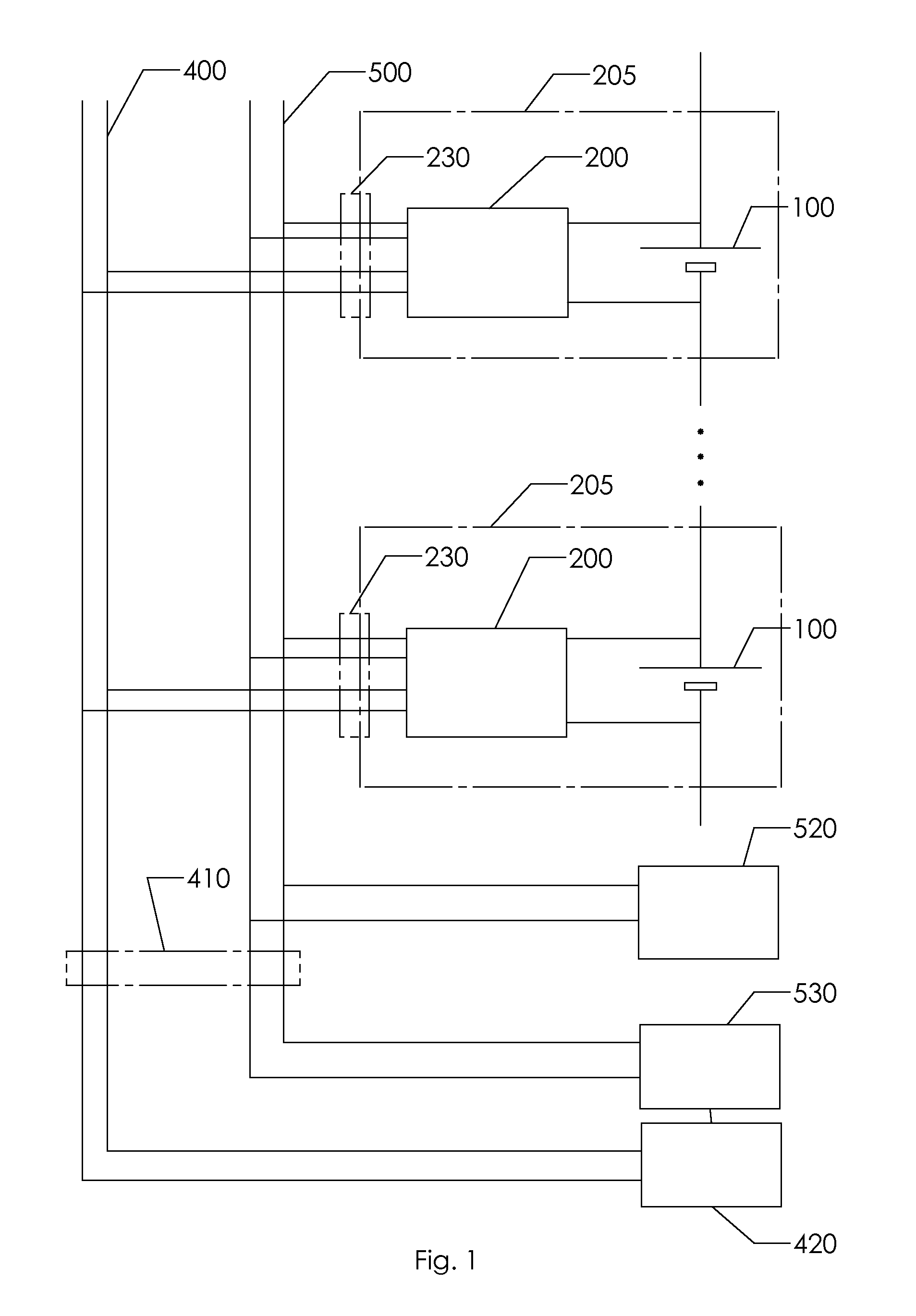
[0010]Each cell together with its corresponding charging module form a complete battery module assembly that can be connected in series with any number of additional assemblies to form a battery pack of desired characteristics. Such battery module assemblies can be readily mass-produced to achieve favorable economies of scale while allowing complete freedom in configuring battery packs of any desired voltage. A failure of any one charging module in a battery pack is readily detectable by a monitoring processor using known methods and need not affect the operation of any other modules. The interconnect requirements are reduced to the common daisy-chained input power bus usually consisting of two or three wires and the common daisy-chained communications bus typically consisting of between two and four wires. Due to the above listed characteristics, the modular charging system of the present invention also meets the second objective.

Problems solved by technology

In such series-connected configurations, problems arise when charging the pack.
If charging is terminated at the point when the smallest-capacity cell reaches full charge, the entire pack will be significantly under-charged.
If bulk charging is continued until the highest-capacity cell is fully charged, the lower-capacity cells will be damaged and may cause hazardous conditions such as fire or explosion.
With sometimes hundreds of cells in a high-voltage pack, such systems are cumbersome, expensive to implement and can be unreliable.
Additionally, the shunting of charging current into a resistive load wastes energy and considerably extends charge time.
A further disadvantage of commonly practiced charging solutions is that a high-power, high-voltage bulk charger is required to convert the typical standard 220V or 110V AC input power into closely regulated DC power supply of a voltage sufficient to charge the entire battery pack.
Such units tend to be heavy, cumbersome and expensive.
As no standard exists at present for high-power vehicle battery packs, each pack configuration usually requires a custom charger design greatly increasing the cost and delaying time to market.
As in other solutions known in the art, this configuration calls for a high-power bulk charger configured specifically to the voltage and power requirements of the entire battery pack, with its corresponding high cost and long time to market.

Method used


Image

  • Modular Charging System for Multi-Cell Series-Connected Battery Packs
  • Modular Charging System for Multi-Cell Series-Connected Battery Packs
  • Modular Charging System for Multi-Cell Series-Connected Battery Packs

Examples


Embodiment Construction

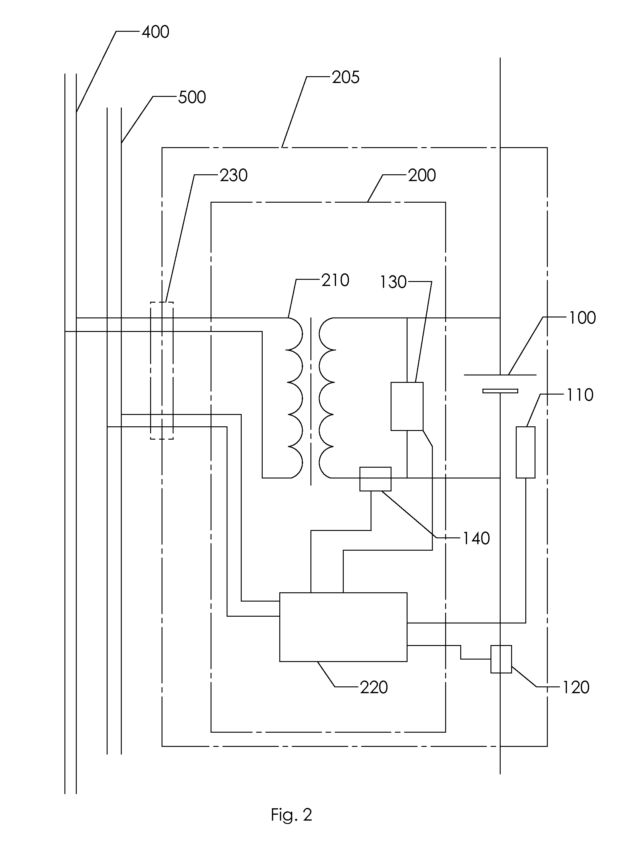
[0018]A representative embodiment of the present invention is illustrated schematically in FIG. 1. A plurality of battery cells 100 are connected in series. Each of the cells 100 is electrically coupled to a corresponding charging module 200, together forming battery module assemblies 205. Each battery module assembly 205 is coupled to the input power bus 400 by means of a connector interface 230. Additionally, modules 205 may interface to a communications bus 500. This communications bus interface may be either by means of additional pins in the physical connector 230, as illustrated, or by any other known means including wireless connections such as Zigbee or BlueTooth. FIG. 1 further shows the power source 420 connected to the power input bus 400 by means of connector interface 410. Numerous embodiments of connector interfaces are known in the art and need not be discussed in detail herein. In most embodiments the power source 420 is a utility power grid supplying single-phase or...


PUM


Abstract

A modular charging system for series-connected battery packs is disclosed. An individual isolated charging module is connected across each cell in the pack. A battery cell and its corresponding charging module form a battery module assembly, a plurality of which are connected in series to form a complete battery pack of desired characteristics. A common input power input bus is shared between all charging modules and is connected in a daisy-chain fashion to a single input power source. A common isolated communications bus, which may be isolated CAN bus, is similarly shared and daisy-chained between all modules, connecting them to a monitoring processor. The monitoring processor is primarily intended to report the condition of each cell to the pack user or operator and need not actively control the charging of any individual cell. Each cell in a pack is optimally charged by the corresponding charging module. The overall system is readily scaled to any desired pack voltage and is well suited to mass production.

Description

[0001]The present invention relates to charging systems for battery packs comprising multiple cells connected in a series configuration, and in particular to electric vehicle battery charging systems.BACKGROUND OF THE INVENTION[0002]A variety of battery types exist in the art. Some of the more commonly used batteries are of Lithium Ion type and its various derivatives. A cell voltage of approximately 3.5V is characteristic of these batteries. The power requirements of applications such as electric vehicles and other high-power loads demand overall pack voltages of over 300V and increasingly of 700V and more. A battery pack for such applications consists of sometimes a hundred or more individual cells connected in series to produce the required pack voltage.[0003]In such series-connected configurations, problems arise when charging the pack. Since no two cells are alike due to production variations, some will reach full charge before others. If charging is terminated at the point whe...

Claims


Application Information

Patent Timeline
Patent Type & Authority Applications(United States)
IPC IPC(8): H02J7/00
CPCH02J7/0004Y02T10/7055H02J7/0018H02J7/00036H02J2310/48H02J7/00047Y02T10/70
Inventor PALATOV, DENNIS
Owner PALATOV POWER SYST
Learn More