Method for manufacturing solar battery cell

a solar battery and manufacturing method technology, applied in the field of manufacturing a solar battery cell, can solve the problems of increasing the thickness the shortening of silicon materials of the solar battery, and the warpage of the solar battery cell, and achieve the effect of high photoelectric conversion efficiency

Inactive Publication Date: 2011-09-29
MITSUBISHI ELECTRIC CORP
View PDF17 Cites 11 Cited by
  • Summary
  • Abstract
  • Description
  • Claims
  • Application Information

AI Technical Summary

Benefits of technology

[0023]According to the present invention, a passivation film composed of a silicon nitride film is formed on one side of a polycrystalline silicon substrate by the plasma CVD method, and a diffusion layer is formed on the other side of the polycrystalline silicon substrate through a thermal diffusion step. Therefore, advantageously, a solar battery having high photoelectric conversion efficiency can be produced by passivating (inactivating) one side of a polycrystalline silicon substrate in a simple step.

Problems solved by technology

A recent increase in market size results in a shortage of silicon materials for solar batteries, and therefore their manufacturers are making efforts to reduce the thicknesses of the solar batteries.
However, since the thermal expansion coefficients of silicon (Si) and an Al—Si alloy (an Al-BSF layer) are different, the warpage of a solar battery cell increases as the thickness of the silicon substrate decreases, and this affects the subsequent module production step.
Therefore, the use of such an Al-BSF layer is quite inconvenient for thin silicon substrates.
Therefore, if this step is applied to polycrystalline silicon substrates, which are the mainstream in the current market, the quality of the crystals is impaired significantly, so that thermal oxidation cannot be applied to solar batteries that use polycrystalline silicon substrates.
However, the oxidation time in the step of forming the silicon oxide film (SiO2) by wet oxidation is several hours, and therefore the mass productivity of this process is not high.

Method used


Image

  • Method for manufacturing solar battery cell
  • Method for manufacturing solar battery cell
  • Method for manufacturing solar battery cell

Examples


first embodiment

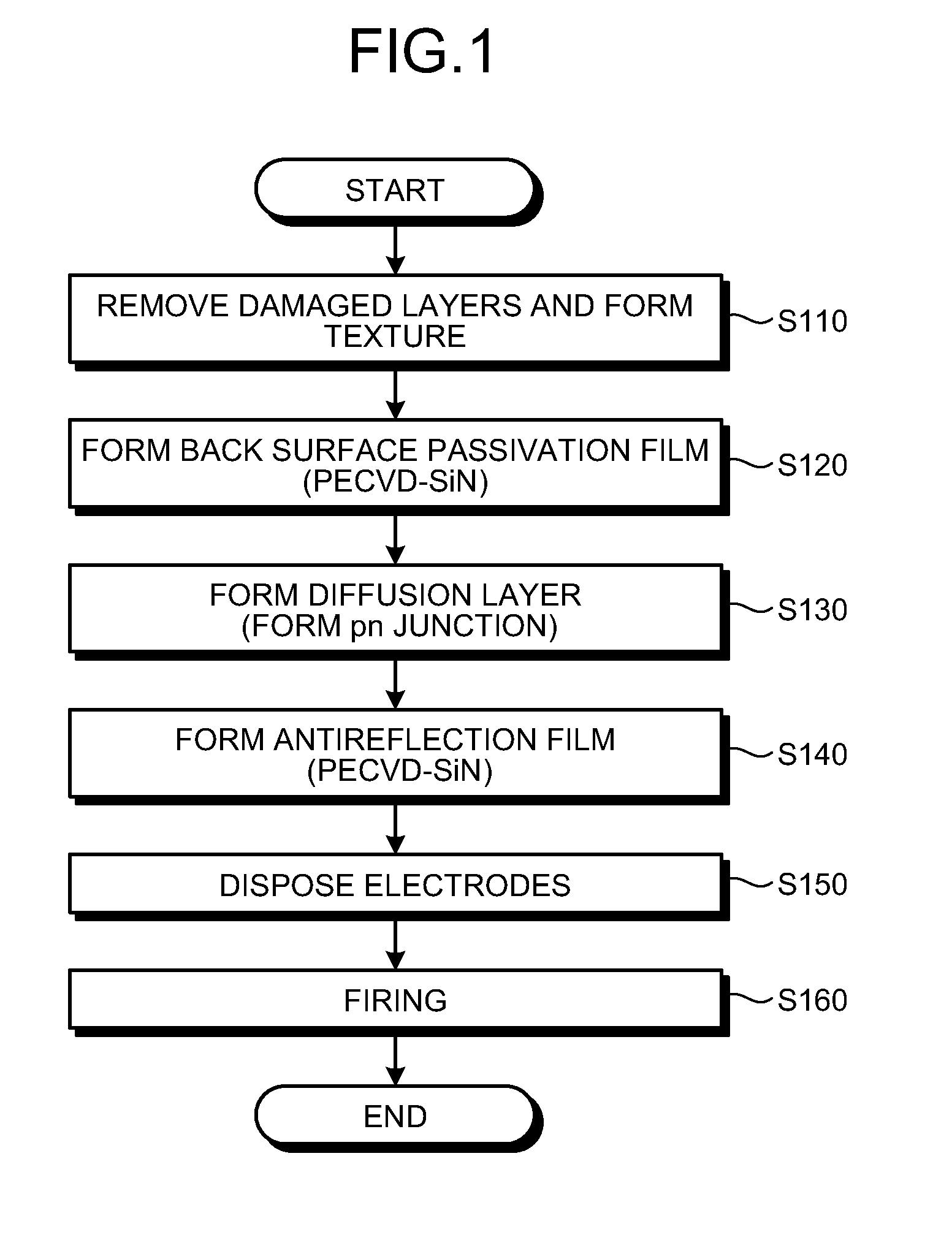
[0067]FIG. 1 is a flowchart describing the method for manufacturing a solar battery cell according to a first embodiment of the present invention. As shown in FIG. 1, the method for manufacturing a solar battery cell according to the present embodiment includes: a damaged layer removing and texture forming step (step S110); a back surface passivation film (PECVD-SiN) forming step (step S120); a diffusion layer forming (pn junction forming) step (step S130); an antireflection film (PECVD-SiN) forming step (step S140); an electrode disposing step (step S150); and a firing step (step S160).

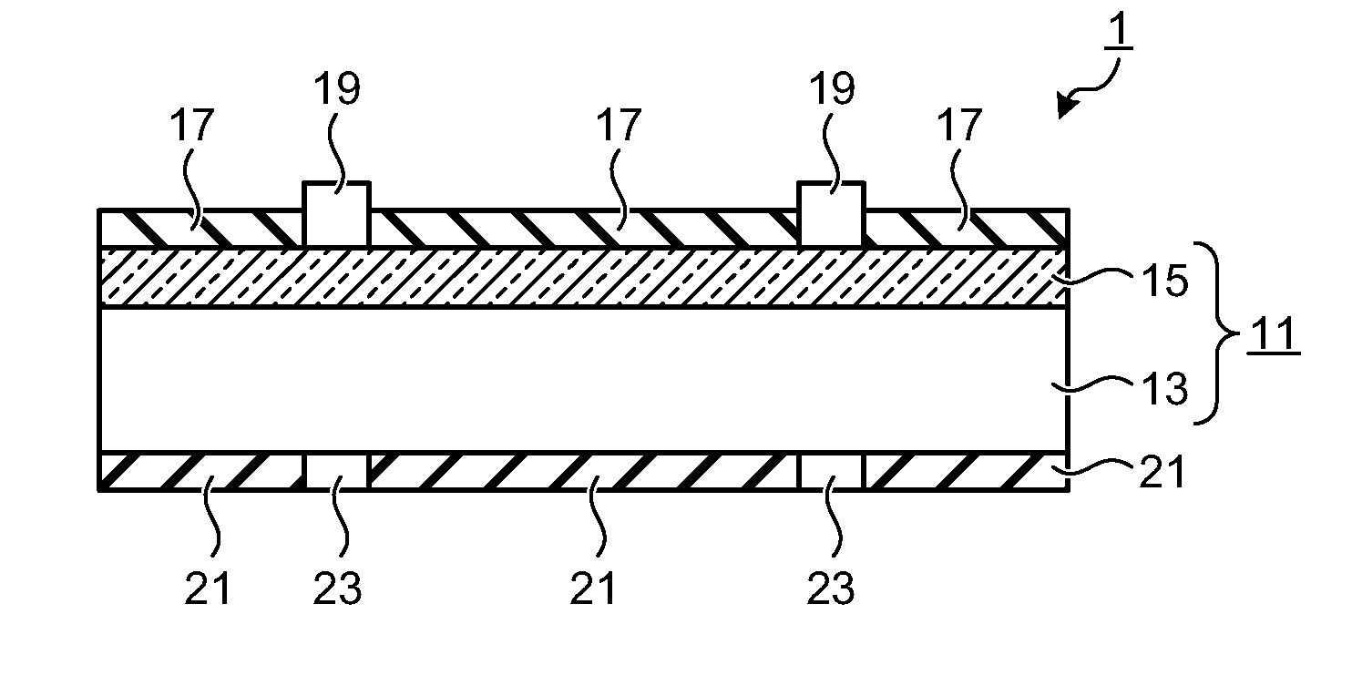
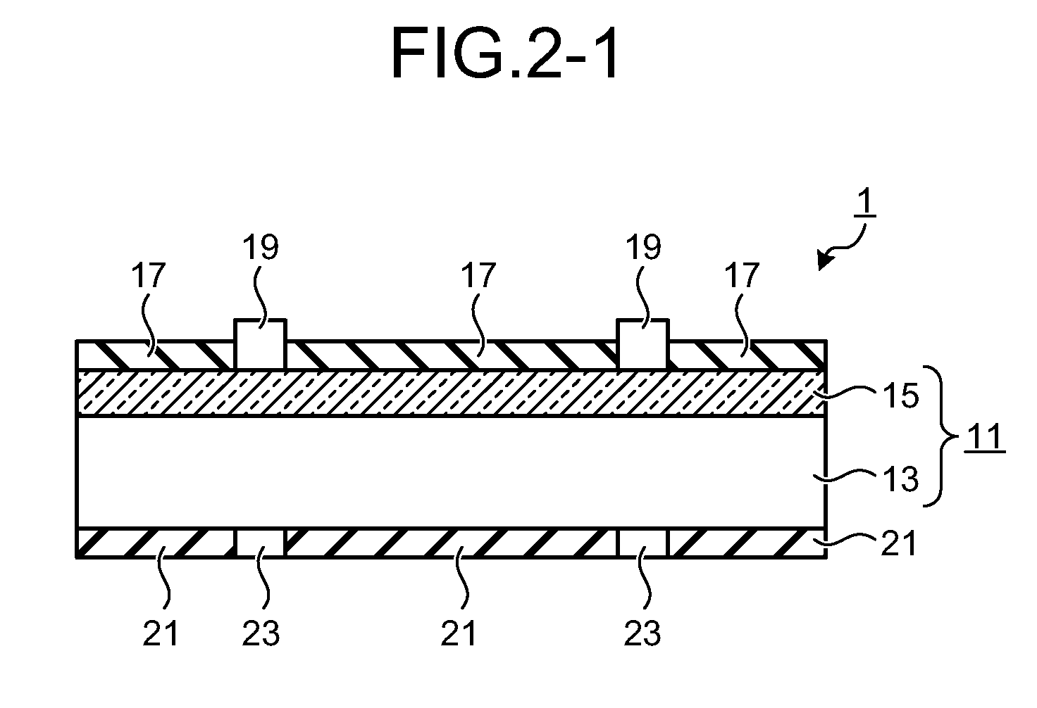
[0068]FIGS. 2-1 to 2-3 are diagrams illustrating the schematic configuration of a solar battery cell 1 produced by the method for manufacturing a solar battery cell according to the present embodiment. FIG. 2-1 is a cross sectional view of the solar battery cell 1, FIG. 2-2 is an upper view of the solar battery cell 1, as viewed from its light receiving surface side, and FIG. 2-3 is a bottom view of ...

second embodiment

[0106]In a second embodiment, to examine the advantages of the method for manufacturing a solar battery cell according to the first embodiment, solar battery cells in Example 2 were produced using the same process as that for the solar battery cells in Example 1. The configuration of the solar battery cells in Example 2 was the same as that of the solar battery cells in Example 1, and the size of the solar battery cells was 4 cm2. Solar battery cells in Comparative Example 2 were also produced, and the output characteristics were compared. The configuration of the solar battery cells in Comparative Example 2 was the same as that of the solar battery cells in Example 2, and the size of the solar battery cells was 4 cm2, which was the same as the size of the solar battery cells in Example 2.

[0107]The solar battery cells in Comparative Example 2 were produced by a conventional process shown in FIG. 8. FIG. 8 is a flowchart describing a method for manufacturing the solar battery cells i...

third embodiment

[0120]In a third embodiment, the dependence on the properties of the PECVD-SiN film serving as the back surface passivation film was examined. For this purpose, solar battery cells in Example 3 were produced by depositing a PECVD-SiN film having a refractive index n of 2.0 on the back surface of a p-type polycrystalline silicon wafer to a thickness of 80 nm to 90 nm. In addition, solar battery cells in Example 4 were produced by depositing a PECVD-SiN film having a refractive index n of 2.2 on the back surface of a p-type polycrystalline silicon wafer to a thickness of 80 nm to 90 nm. The solar battery cells in Examples 3 and 4 were produced by the same process as that for the solar battery cells in Example 1. The structures of the solar battery cells in Examples 3 and 4 were the same as the configuration of the solar battery cells in Example 1, and the size of each battery cell was 4 cm2.

[0121]Conventional solar battery cells (Comparative Example 3) each having an Al-BSF layer disp...


PUM

PropertyMeasurementUnit
refractive indexaaaaaaaaaa
temperatureaaaaaaaaaa
thicknessaaaaaaaaaa

Abstract

A method includes: a first step of forming a passivation film on a first surface of a crystalline silicon substrate of a first conductive type; a second step of diffusing an element of a second conductive type into a second surface of the crystalline silicon substrate by thermal diffusion to form a diffusion layer, whereby a pn junction is formed; a third step of forming an antireflection film on the diffusion layer; a fourth step of disposing a first electrode paste on the second surface of the crystalline silicon substrate; a fifth step of disposing a second electrode paste on the passivation film; and a sixth step of firing the first electrode paste and the second electrode paste to form electrodes.

Description

TECHNICAL FIELD[0001]The present invention relates to a method for manufacturing a solar battery cell, and in particular, to a method for manufacturing a solar battery cell in which a crystalline silicon substrate serving as a solar battery substrate has a passivated (inactivated) back surface.BACKGROUND ART[0002]To improve the efficiency of solar batteries, it is necessary to suppress recombination of carriers. In most crystalline silicon solar batteries currently commercially available, a high concentration diffusion layer of the same conductive type as that of the substrate of the solar battery is provided on the back surface of the substrate to remove minority carriers on the back surface of the substrate by the built-in potential of the junction, whereby recombination on the back surface of the substrate is suppressed. The high concentration diffusion layer on the back surface of the substrate is referred to as a BSF (Back Surface Filed) layer.[0003]In a typical silicon solar b...

Claims


Application Information

Patent Timeline
Patent Type & Authority Applications(United States)
IPC IPC(8): H01L31/18
CPCH01L31/02168H01L31/068Y02E10/547H01L31/1868H01L31/1804Y02E10/546Y02P70/50
Inventor NISHIMOTO, YOICHIRO
Owner MITSUBISHI ELECTRIC CORP
Why Eureka
Try Eureka