Heat exchanger structure and isothermal compression or expansion chamber

a technology of heat exchanger and isothermal compression or expansion chamber, which is applied in the direction of moving conduit heat exchanger, lighting and heating apparatus, engine cooling apparatus, etc., can solve the problems of low heat pump cycle efficiency and real systems are far from being able to enable iso-thermal compression or expansion, etc., to achieve wide operating range, low loss, and high efficiency

Inactive Publication Date: 2011-10-06
STIRAL
View PDF3 Cites 12 Cited by
  • Summary
  • Abstract
  • Description
  • Claims
  • Application Information

AI Technical Summary

Benefits of technology

[0015]An object of an embodiment of the present invention is to provide a thermodynamic engine with low losses and a high efficiency over a wide operating range.

Problems solved by technology

A problem linked to current Stirling engines is that, when they have a good engine cycle efficiency, they will have a low heat pump cycle efficiency, and conversely.
Low efficiencies in the reversible use of such engines or in their use over a wide operating range originate from the different losses occurring therein and, especially, from temperature differences in heat exchanges.
Another source of irreversible losses in Stirling engines and in any engine implementing theoretically isothermal compressions and expansions is that real systems are far from being capable of enabling such iso-thermal compressions and expansions.

Method used


Image

  • Heat exchanger structure and isothermal compression or expansion chamber
  • Heat exchanger structure and isothermal compression or expansion chamber
  • Heat exchanger structure and isothermal compression or expansion chamber

Examples


Embodiment Construction

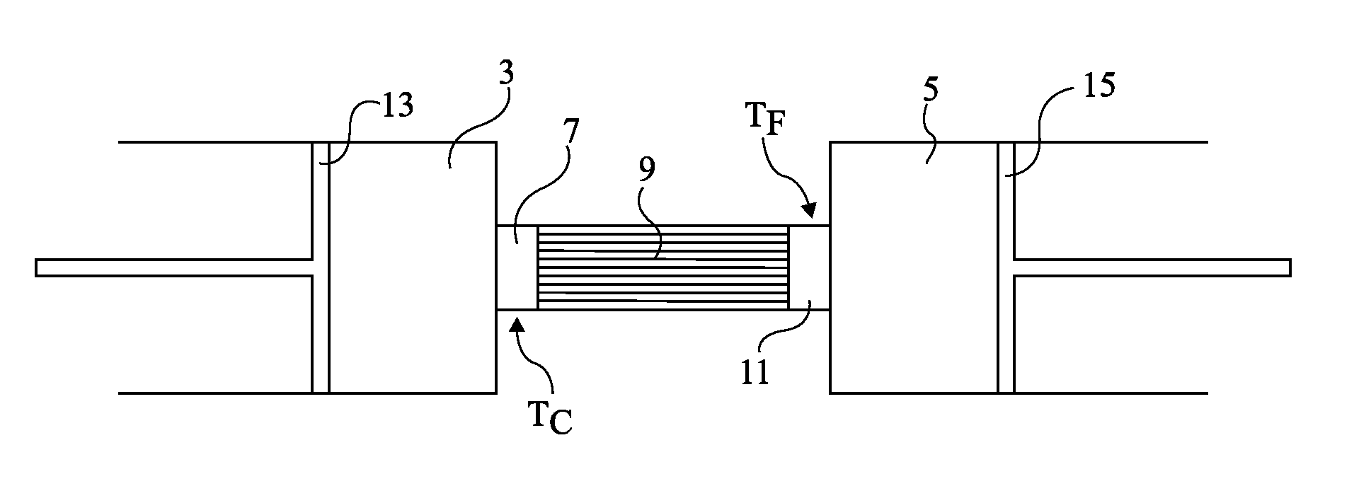
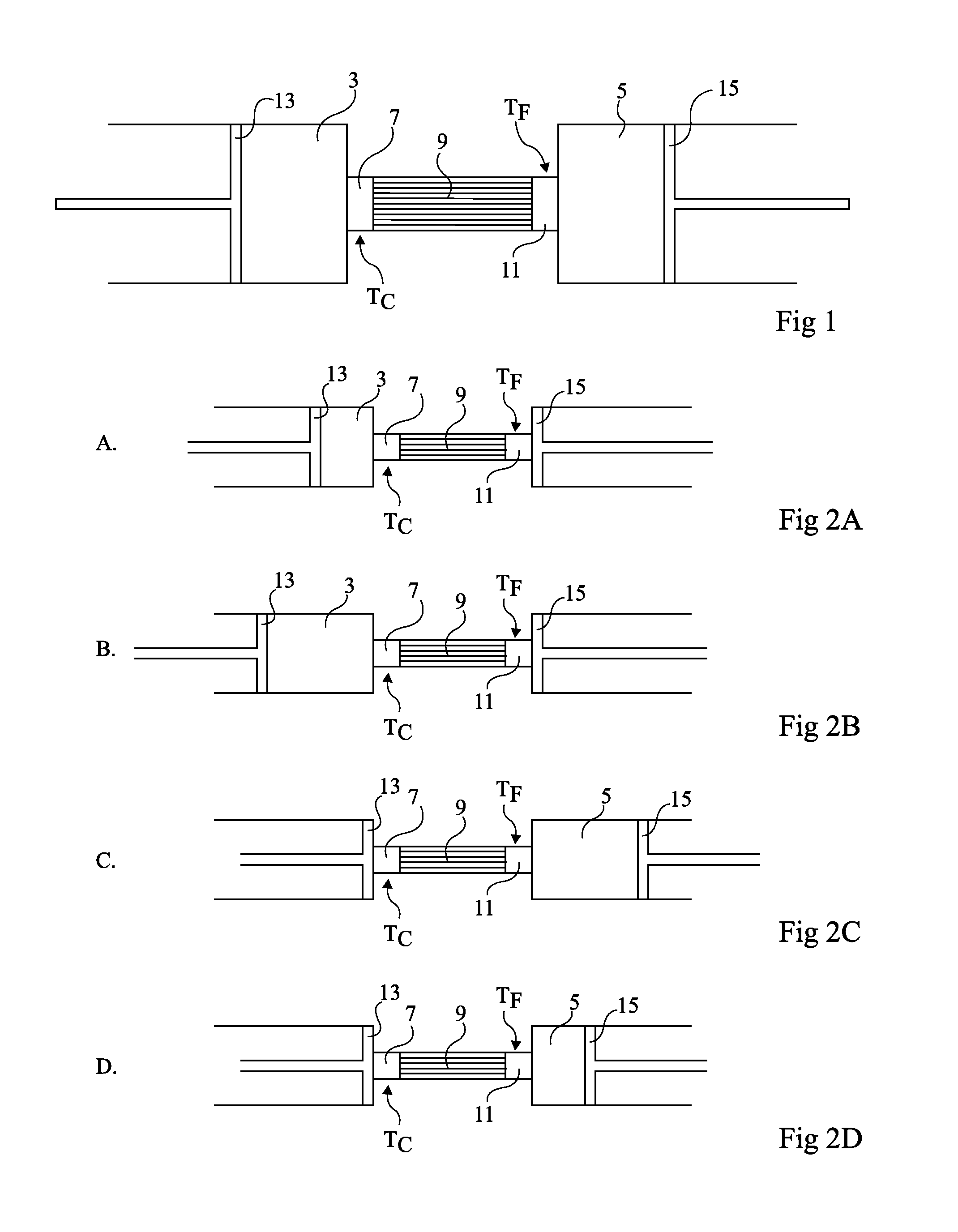
[0041]An embodiment of the present invention first provides directly placing heat exchangers in compression and expansion chambers. It further provides forming compression and expansion chambers in which the exchangers comprise many portions forming partitions in the chambers. Such partitions extend from two opposite walls of the chambers and interleave when the chamber volume decreases.

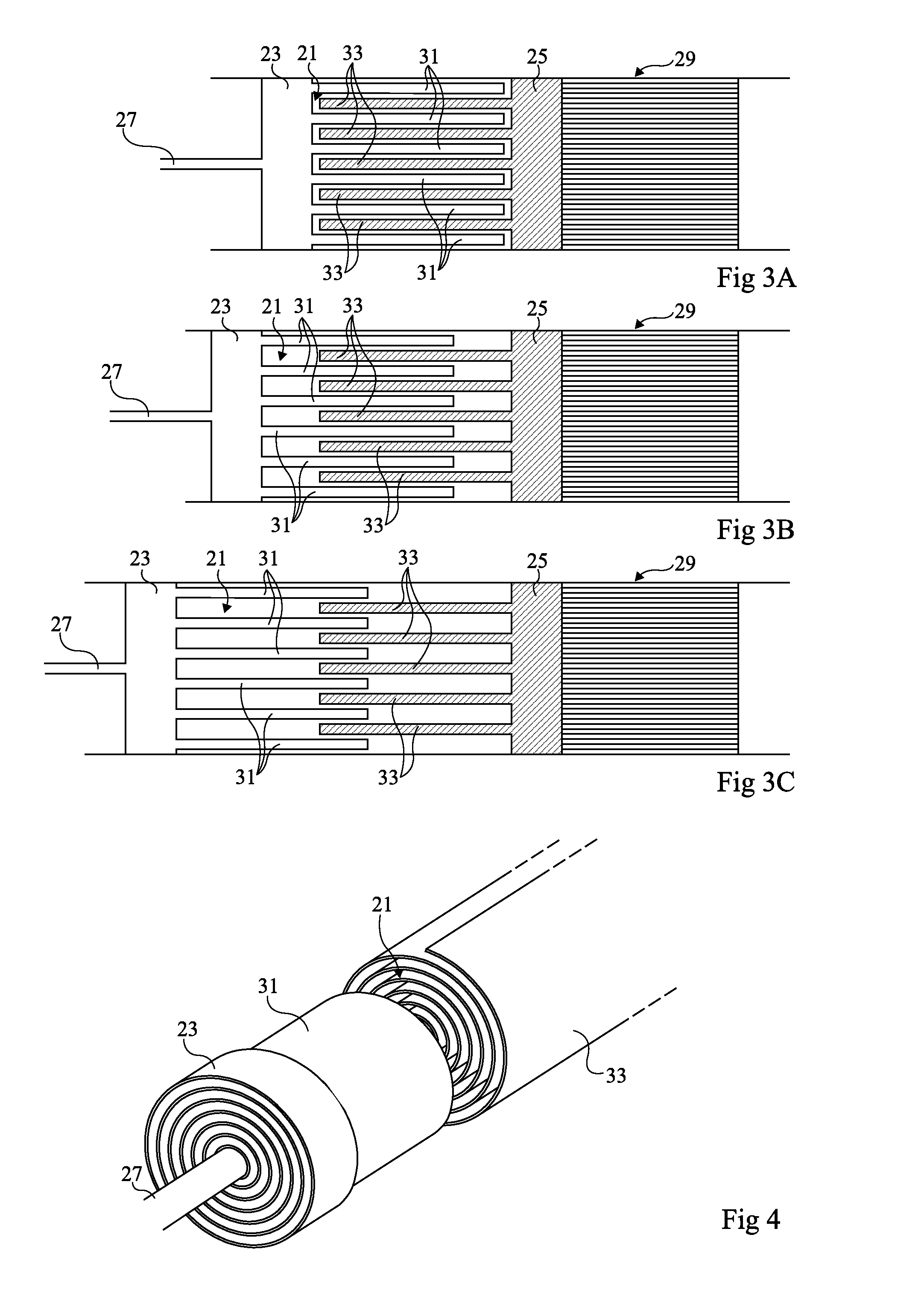
[0042]FIGS. 3A to 3C illustrate, in longitudinal cross-section view, a compression or expansion chamber such as described hereabove forming, for example, a portion of a Stirling engine. These drawings illustrate different states in an isothermal expansion.

[0043]In FIG. 3A, a chamber 21 is formed in a cylinder and is delimited by two walls 23 and 25 mobile with respect to each other in the cylinder. The shown example considers a mobile wall 23 associated with a piston axis 27, and a fixed wall 25, fixed with respect to a regenerator 29 (not detailed). It should be understood that walls 23 and 25 may b...


PUM


Abstract

A thermodynamic machine includes at least one chamber in which an isothermal expansion and/or compression is to be carried out, said chamber being longitudinally defined by first and second walls that are mobile relative to each other. The chamber is divided by partitions extending longitudinally from each of the first and second walls, the partitions being interleaved within each other, and the distance between the partitions extending from a same wall being such that the ratio between the distance squared and the cycle duration of the thermodynamic machine is lower than the average thermal diffusivity of the gas contained in the chamber.

Description

FIELD OF THE INVENTION[0001]The present invention generally relates to a heat exchanger structure. The present invention also relates to a chamber in which isothermal compressions and / or expansions are performed. The present invention further relates to a high-efficiency reversible thermodynamic engine comprising such a chamber, for example, a Stirling engine.DISCUSSION OF PRIOR ART[0002]Stirling engines are sometimes used for industrial refrigeration and in military or space applications. Such engines have the advantage of being usable as motors or to generate heat or cold without the use of refrigerants, which are generally polluting. Another advantage of a Stirling engine is that its hot source is external and that this source can thus be obtained by means of any known fuel type, or even solar radiation.[0003]In a Stirling cycle, a gas, for example, air, hydrogen, or helium, is submitted to a four-phase cycle: an isochoric heating, an isothermal expansion, an isochoric cooling, a...

Claims


Application Information

Patent Timeline
Patent Type & Authority Applications(United States)
IPC IPC(8): F02G1/055
CPCF02F3/28F02G1/053F02G1/055F28F21/04F02G2256/02F28D11/06F02G2255/20
Inventor CHARLAT, PIERRE
Owner STIRAL
Why Eureka
Try Eureka