Method and system for compensating ageing effects in light emitting diode display devices

a technology of light-emitting diodes and display devices, applied in the field of methods and systems for compensating ageing effects of light-emitting diodes display devices, can solve the problems of insufficient existence, increased failure rate, severe cost implications, etc., and achieve the effect of accurate correction and memory us

Active Publication Date: 2011-10-06
BARCO NV
View PDF6 Cites 98 Cited by
  • Summary
  • Abstract
  • Description
  • Claims
  • Application Information

AI Technical Summary

Benefits of technology

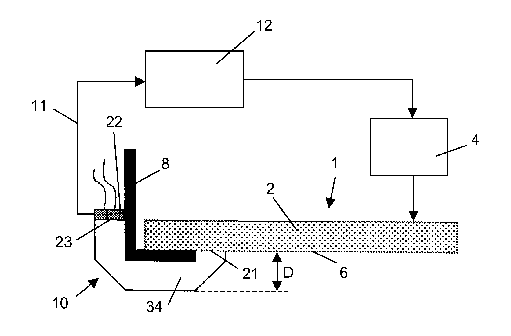
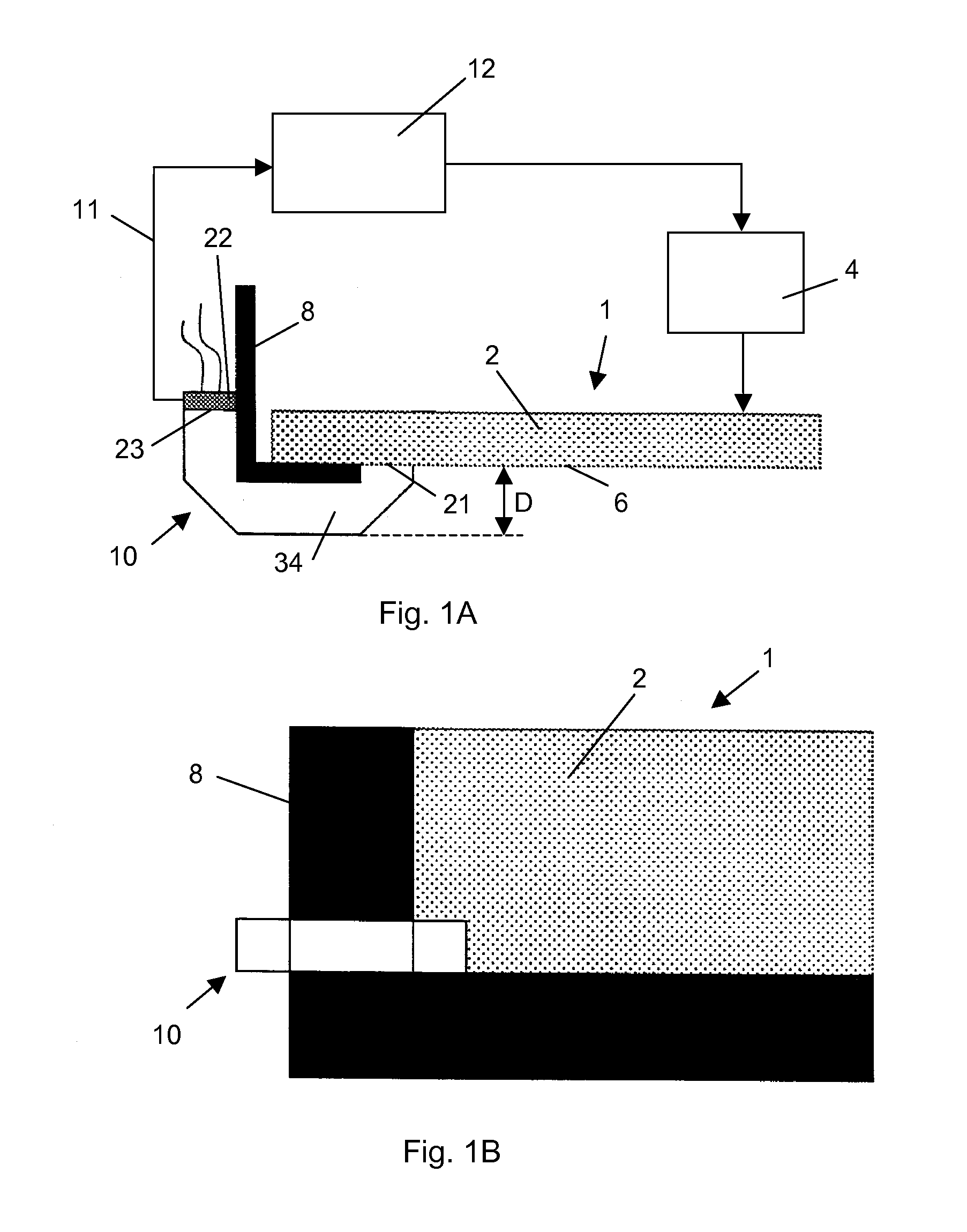
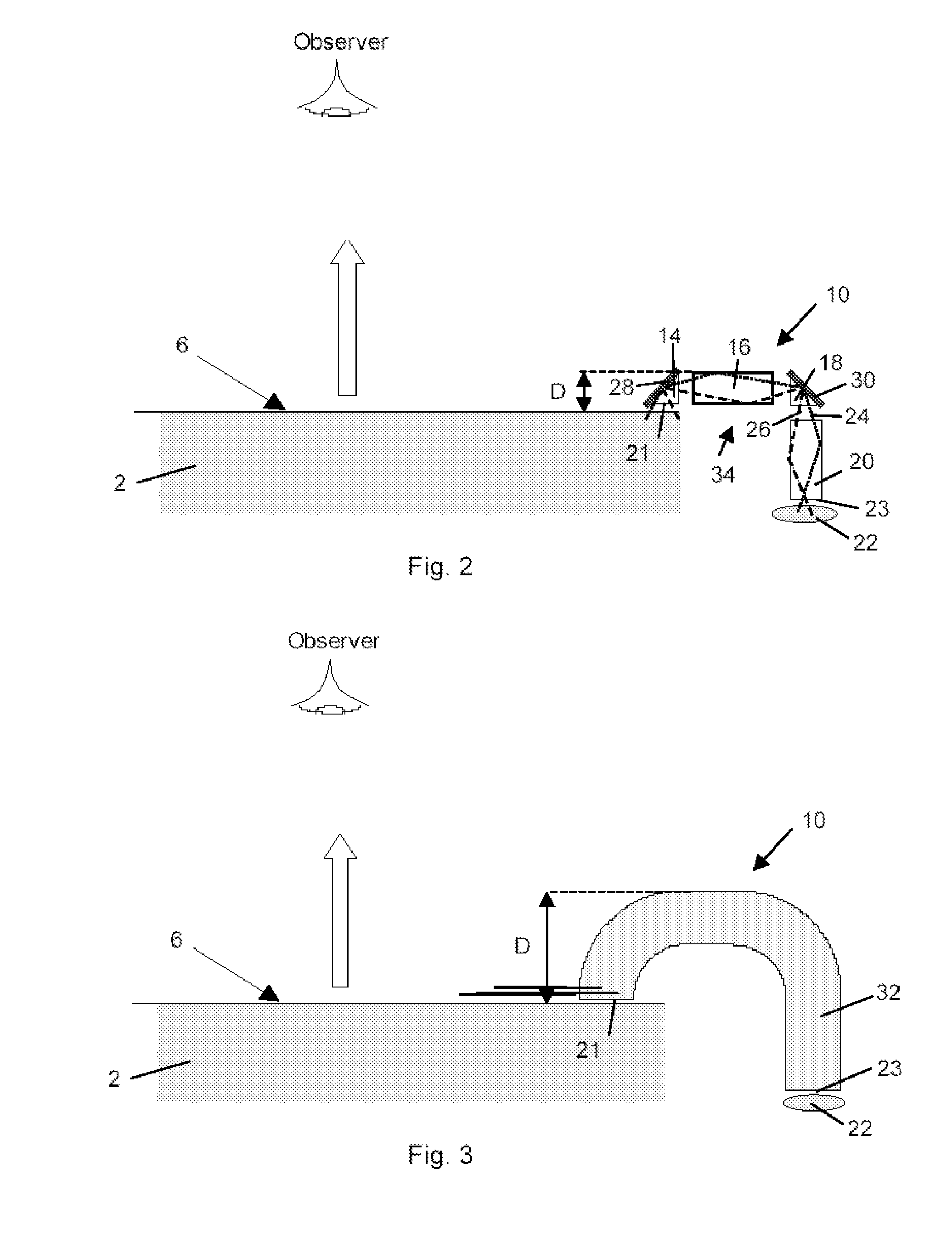
[0018]A light sensor faces the sub-area of the screen, for instance in a corner of the screen, and measures the light coming from this small sub-area. The pixels such as OLED pixels of the sub-area are driven to give a small image that is representative of the image on the complete screen. This small image e.g. can be obtained by resealing the first display image to a smaller size (second display image). The exact scaling algorithm used is not considered a limitation of the present invention. Based on the actual display contents the typical driving values can be identified for each pixel or a representative group of pixels of the sub-area and the actual behaviour of these pixels can be determined at any moment of the drive time. Like that, a more accurate correction especially for the differential ageing effects is achieved without the need to integrate a sensor in each individual pixel of the complete screen and without storing the drive history of each pixel of the complete screen.
[0019]In a preferred embodiment of the present inventive method the sub-area can again be divided into different parts which are driven with a pattern based on the actual display contents. Typical driving values such as a dynamic pattern like moving images, or temporal dither patterns of the actual displayed image can be identified for this purpose and at least one part of the sub-area of the display device can be driven with that pattern. At the same time, for each individual pixel of the sub-area the data how the pixel has been driven over the lifetime of the display can be stored. By measuring characteristics of the test patterns, parameters of an aging model can be estimated. These parameters then can be used, in combination with information on how display pixels have been driven over the lifetime of the display, to predict the aging behaviour of display pixels. In contrast to making an estimated prediction of the actual behaviour based on a model only, with the method of the present invention now a measurement of the current behaviour of a given class of pixels like blue pixels at the top of the display device can be provided instead of storing the complete driving behaviour of each pixel of the complete display and instead of an inaccurate estimation based on a current measurement and / or a model. Moreover, the memory used to store the driving history of each of the sub-area pixels or alternatively of classes of these pixels from parts of the sub-area can be reduced.

Problems solved by technology

This is a problem that much less exists with LCD display devices to the same degree.
Obviously, the higher the current to drive the pixel for compensating the loss of performance due to ageing, the faster the pixel ages further so as the pixel reaches the end of its life the failure becomes more rapid.
While this approach is very accurate it has severe drawbacks in terms of cost implications, scaling and reducing the size of the pixels for higher resolutions, and complicated drive and production processes.
Therefore, in practice this second method does not show very accurate results and still some part of the differential ageing problem remains visible.
Thus, this type of compensation would not be acceptable for display devices used in medical imaging.
The method is based on the measurement of total current for a group of pixels which has the drawback that only an estimation for the actual behaviour of the OLED pixels can be used depending on the measured current.
That again results in a complicated built showing the above mentioned drawbacks for the sensor based correction method.
Moreover, the method can not include information about the past operation of the OLED pixels to compensate for the degradation.
Thus, the compensation achieved is not as accurate as it is required for an application in medical imaging.

Method used


Image

  • Method and system for compensating ageing effects in light emitting diode display devices
  • Method and system for compensating ageing effects in light emitting diode display devices
  • Method and system for compensating ageing effects in light emitting diode display devices

Examples


Embodiment Construction

[0064]The present invention will be described with respect to particular embodiments and with reference to certain drawings but the invention is not limited thereto but only by the claims. The drawings described are only schematic and are non-limiting. In the following the acceptance angle of a sensor refers to the angle subtended by the extreme light rays which can enter the sensor. The angle between the optical axis and the extreme rays is therefore usually half of the acceptance angle.

[0065]FIG. 7 is a schematic representation of a display system, e.g. an OLED display that can be used with the present invention including a signal source 48 a controller unit 46, a driver 44 and a display 42 with a matrix of pixel elements that are driven by the driver 44. The invention makes use of a sub-area (patch) of the screen in a way that is optimised for / adapted to emissive displays. The sub-area is a measurement zone that contains more than 1 pixel, and spatial intelligence is added to the...


PUM


Abstract

The present invention relates to a method for compensating ageing effects of pixel outputs displaying an image on a display device. The method involves displaying a first image on an active display area (6) on the display device (1) having a first plurality of pixels; displaying a second image on a sub-area (7) of the display device (1) and having a second plurality of pixels, the active display area (6) being larger than the sub-area (7) and the second image being smaller than the first image and having fewer pixels than the active display area (6); driving the pixels of the sub-area (7) with pixel values that are representative or indicative for the pixels in the activity display area (6); making optical measurements on light emitted from the sub-area (7) and generating optical measurement signals (11) therefrom, and; controlling the display of the image on the active display area (6) in accordance with the optical measurement signals (11) of the sub-area (7).

Description

TECHNICAL FIELD OF THE INVENTION[0001]The present invention relates to a system and method for detecting and / or visualising and / or compensating ageing effects of an image displayed on a display device subject to ageing such as an OLED display. It applies more particularly, but not exclusively, to active matrix type OLED displays intended to be used for medical imaging.[0002]More particularly, the present invention relates to a display device that has a high contrast ratio, wide viewing angle, extremely fast response time, and accurate imaging over the whole lifespan of the display device.BACKGROUND OF THE INVENTION[0003]At present, it is known that OLED displays can be equipped with means for compensating the loss of luminescence due to ageing, whereby such compensation in part is carried out in view of the differential ageing of the individual pixels. The differential ageing of the individual pixels occurs due to the different drive levels of each pixel over the lifespan of the dis...

Claims


Application Information

Patent Timeline
Patent Type & Authority Applications(United States)
IPC IPC(8): G09G3/30G06F3/038
CPCG09G3/3208G09G2310/0227G09G2320/0242G09G2320/0285G09G2320/029G09G2360/145G09G2320/043G09G2320/048G09G2320/0693G09G2360/144G09G2320/041
Inventor BERT, TOMKIMPE, TOM
Owner BARCO NV
Why Eureka
Try Eureka