Fuel system and method

a fuel system and fuel technology, applied in the field of fuel systems, can solve problems such as potential fire/explosion hazards

Active Publication Date: 2011-10-20
AIRBUS OPERATIONS LTD
View PDF3 Cites 7 Cited by
  • Summary
  • Abstract
  • Description
  • Claims
  • Application Information

AI Technical Summary

Benefits of technology

[0020]Waste heat from the catalytic reaction may he used to prevent icing of components of the dehumidifying device, e.g. the discharge tube and/or the re

Problems solved by technology

The ullage can contain reactive components, such as oxygen and/

Method used


Image

  • Fuel system and method
  • Fuel system and method
  • Fuel system and method

Examples


Embodiment Construction

)

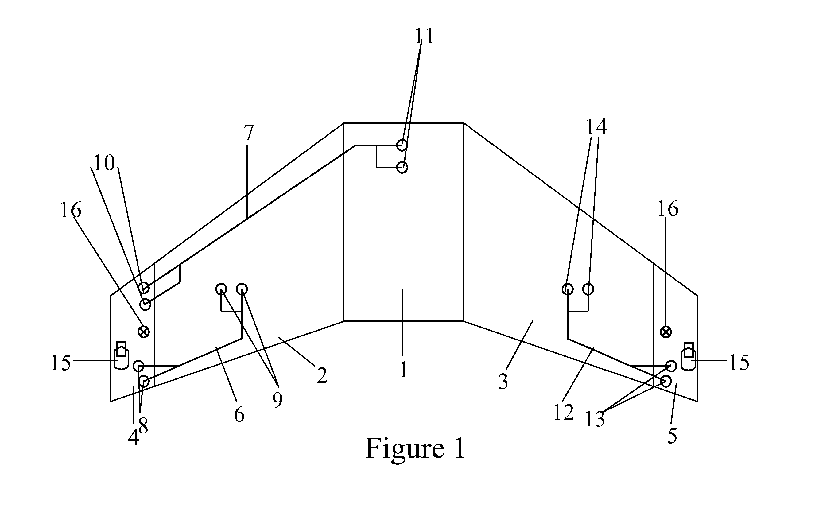
[0031]FIG. 1 shows a general ventilation system architecture for a three-tank configuration of an aircraft fuel system. The fuel system includes a centre tank 1, a left wing tank 2 and a right wing tank 3. The ventilation system includes a left vent tank 4 and a right vent tank 5. The left vent tank 4 ventilates the centre tank 1 and the left wing tank 2 by means of ventilation pipes 6, 7 which open into ventilation inlets 8, 9, 10, 11, The right vent tank 5 ventilates the right wing tank 3 by means of ventilation pipe 12 which opens into ventilation inlets 13 and 14.

[0032]Each vent tank 4, 5 includes a NACA duct assembly 15 including a NACA vent, or NACA scoop, which opens to the atmosphere on the lower aerodynamic surface of the aircraft wing. The vent tanks 4, 5 further include an over pressure protector 16.

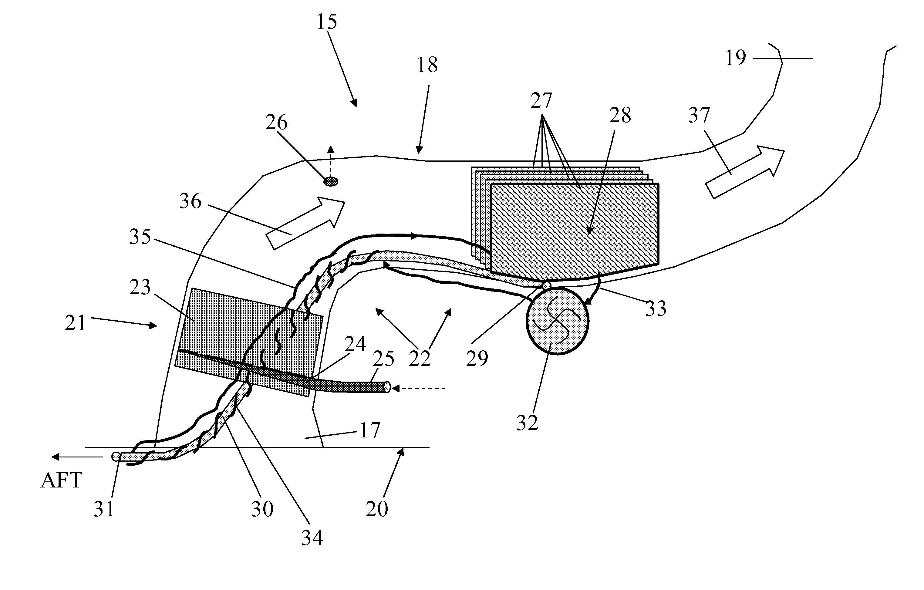
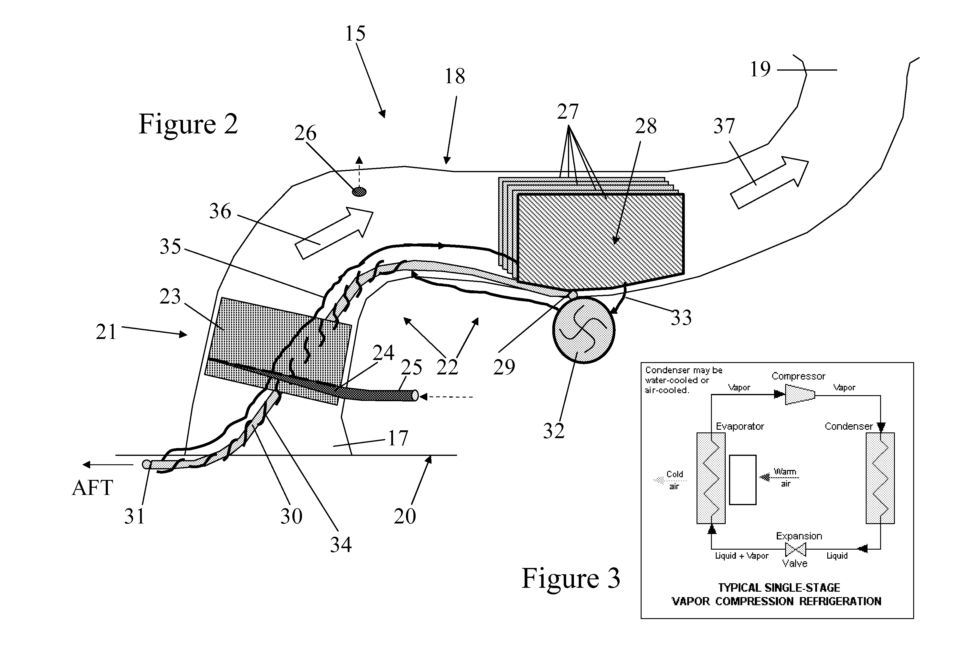
[0033]One of the NACA duct assemblies 15 is shown schematically in FIG. 2, The NACA duct assembly 15 includes a vent (or inlet) 17, a duct 18, and a “bellmouth” outlet 19. Th...


PUM

PropertyMeasurementUnit
Contentaaaaaaaaaa
Heataaaaaaaaaa

Abstract

A fuel system includes a fuel tank, a vent tank fluidically connected to the fuel tank ullage, the vent tank having a duct open to the ambient atmosphere and the interior of the vent tank, and a catalyst disposed in the duct, wherein the catalyst is adapted to deplete one or more reactive components of gas flowing through the duct by catalytic reaction. Also, a method for depleting one or more reactive components of gas in the fuel system, includes depleting one or more reactive components of gas flowing through the duct using the catalyst.

Description

FIELD OF THE INVENTION[0001]The present invention relates to a fuel system and to a method for depleting one or more reactive components of gas in a fuel system.BACKGROUND OF THE INVENTION[0002]Fuel tanks for storing liquid fuel are used, for example, for transporting or storing fuel and on vehicles for their propulsion systems. The volume of gas above the liquid fuel within the fuel tank is known as the ullage. The ullage can contain reactive components, such as oxygen and / or fuel vapours, which can be a potential fire / explosion hazard. The term “inerting” refers to the process of depleting one or more of these reactive components to reduce this potential hazard.[0003]Various inerting systems are known in the art. For example, the potentially explosive atmosphere in the ullage can be displaced by the addition of inert gas, such as Argon, Nitrogen, or Carbon dioxide. Particularly in the case of vehicle fuel systems, the ullage volume increases as the liquid fuel is consumed and so t...

Claims


Application Information

Patent Timeline
IPC IPC(8): B01D53/86B01D53/46B01J19/00
CPCB01D53/265B01D53/75B01D53/8668B01D53/8671B01D2259/4575B01D2257/104B01D2257/7022B01D2258/02B01D2255/10
Inventor TICHBORNE, FRANKLINLAM, JOSEPH K-WPARMENTER, DAVIDMASTERS, SIMON
Owner AIRBUS OPERATIONS LTD
Why Eureka
Try Eureka