[0015]In another exemplary embodiment, uncooled
infrared detectors and
focal plane arrays may be provided in which an optically transitioning
filter element may be suspended over a corresponding
microbolometer pixel
membrane structure of an
infrared detector element, i.e., a separate suspended optically transitioning
filter element may be provided that corresponds to each of multiple detector elements of a focal plane array (FPA) in a one-to-one relationship (i.e., a separate optical element provided for each respective detector element of the FPA such that each optical element is suspended over and above radiation detection circuitry of the respective detector element and is not suspended over and above the radiation detection circuitry of other adjacent detector elements, and such that each optical element only filters or focuses radiation destined for the underlying radiation detection circuitry of the respective radiation detector element and not any other radiation detector elements of the FPA). An optically transitioning
filter element may be structurally attached by an electrically and / or thermally insulating interconnect to existing
metal interconnects. In this way, the installation of the optically transitioning filter element substantially does not
impact the
thermal mass or degrade the thermal
time constant of the
microbolometer pixel structure and does not require any additional device real estate area beyond the area originally consumed by the microbolometer pixel structure interconnects so as to preserve the original infrared absorbing
fill factor of the microbolometer pixel structure.
[0016]Pixel-level optically transitioning filter elements may be employed to achieve real time filtering of radiation in an active manner without adding significant optical
crosstalk effects, without degradation (i.e., increasing) of the detector thermal
time constant, and / or in a manner that allows for thermal response tuning independent of the detector pixel. Such active pixel-level filtering may be implemented by providing a multi-
level structure that includes a thermally and electrically isolated optically transitioning filter element that is suspended over a microbolometer pixel
membrane structure of a corresponding
infrared detector element, i.e., in a one-to-one relationship (i.e., one optical element provided for each underlying detector element). Such an embodiment may be advantageously implemented to provide optically transitioning pixel-level filter elements to enable one or more features such as spectral infrared radiation detection and / or selective radiation
immunity.
[0017]Optically transitioning filter elements disclosed herein may be controlled by the properties of a selected optically transitioning material or materials, i.e., the optically transitioning material transmits radiation at temperatures below the
transition temperature of the material while it reflects at one or more specific radiation
wavelength bands at temperatures above the
transition temperature of the material. Since the thermal response is a result of the thermal flux of the radiation and the
thermal isolation of the filter element (e.g., including optically transitioning filter or combination of optically transitioning and passive filters), it therefore can be controlled with
thermal isolation structures / forms. In this regard, an optically transitioning filter element may be suspended by one or more low
thermal conductivity or thermally insulating support interconnect / s and
thermal isolation structures / forms in a manner such that the optically transitioning filter element substantially does not affect the thermal
time constant of the underlying microbolometer pixel structure. Furthermore, the thermal isolation structure / forms may be implemented to allow for the tuning of the thermal response of the optically transitioning filter element to the flux of the radiation in a manner that is independent of the response of the underlying microbolometer pixel structure to the
radiation flux.
[0019]To prevent such damage, individual detector elements (e.g., of a focal plane array) may be provided in one exemplary embodiment with optically transitioning filter elements that are composed of an optically transitioning material that remains substantially transmissive to desired radiation wavebands (e.g., indirect reflected
sunlight, artificial room lighting, etc.), but that becomes substantially non-transmissive or opaque to undesired radiation wavebands (e.g., direct
sunlight, electrical arc radiation, etc.). In such an embodiment, the optically transitioning filter may be configured in a manner that it sufficiently dissipates heat when exposed to desired radiation wavebands at normal
operating temperature such that the optically transitioning material remains below its
optical transition (e.g.,
phase transition) temperature and in a corresponding substantially transmissive state, but also in a manner such that
exposure to radiation of an undesired bandwidth generates sufficient heat that cannot be dissipated rapidly enough to prevent the temperature of the phase transitioning material from increasing above its
optical transition (e.g.,
phase transition) temperature and becoming at least partially non-transmissive or opaque to the undesired radiation. In this way, the optically transitioning filter acts to transmit desired radiation to the underlying detector circuitry, but automatically shields the underlying detector circuitry from the undesired radiation.
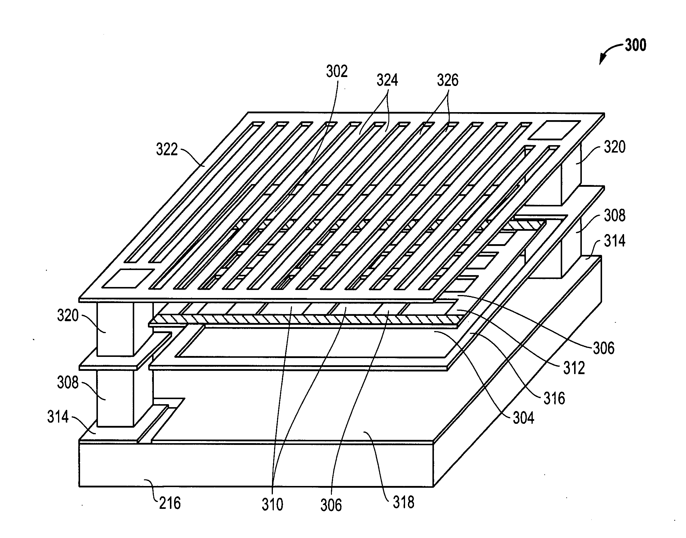
[0021]In one exemplary embodiment, a multi-layer structure may be provided that includes an optically transitioning filter element layer that is optionally combined with other
layers of optically transitioning, passive or combination passive / optically-transitioning optical elements that each filter different wavelengths. Whether provided alone or in combination with other suspended optical elements, a multilayer optically transitioning structure (or other type of suspended optical element disclosed herein) may be provided that is thermally isolated and positioned in close proximity (e.g., less than about 10 microns in one embodiment, less than about 10 microns and greater than or equal to about 1 micron in another embodiment, from about 1 micron to about 10 microns in another embodiment, less than or equal to about 5 microns in another embodiment, from about 1 micron to about 5 microns in another embodiment; about 2 microns in another embodiment, less than or equal to about 2 microns in another embodiment; and from 1 micron to about 2 microns in another embodiment) to an underlying microbolometer pixel structure or other type of detector circuitry to reduce cross talk between adjacent pixels of a FPA.
[0023]In one exemplary embodiment, a monolithic optically transitioning filter element may be fabricated using modern photolithographic techniques so that precise registration and alignment of the optically transitioning filter element over a
bolometer pixel is achieved. In another embodiment, the suspended optically transitioning filter element may be disposed in sufficiently close proximity (e.g., about 2 microns in one embodiment, less than or equal to about 2 microns in another embodiment) to the underlying detector circuitry (e.g., microbolometer pixel structure) to minimize or substantially eliminate cross talk between adjacent pixels of a FPA. However, a suspended optically transitioning filter element may be disposed at any other greater or lesser distance relative to a microbolometer pixel
membrane structure, e.g., as may be appropriate to
optical focusing requirements for a given application.

